Threshold Tab
The Threshold Unit tab allows the user to define discrimination conditions and logical operations on a selection of input signals and output the result as TTL signals in real time. This functionality and tab is available on all MF instruments.
Features
- 4 threshold units for state detection
- analog input signals: demodulator data (X, Y, R, Θ), PID data (error, output, shift; requires MF-PID Quad PID/PLL Controller option option)
- digital input signals: 32 DIO channels, input and output overflows, etc.
- threshold detection: above, below, inside, outside, rising edge, falling edge
- absolute value and low-pass filtering can be applied prior to threshold detection
- configurable activation and deactivation times
- combination of up to 3 logical signals on one output with NOT, AND, OR, and XOR operation
- minimum length, hold, and invert functionality
Description
The Threshold tab enables real-time logical analysis of measurement data in order to detect special conditions or failures, and trigger a reaction via a TTL output. Typical applications are AFM tip protection or microfluidics cell sorting. Whenever the tab is closed or an additional one of the same type is needed, clicking the following icon will open a new instance of the tab.
| Control/Tool | Option/Range | Description |
|---|---|---|
| Threshold | Configure the threshold unit and the logical combinations to generate digital output signals. |
The Threshold tab (see Figure 1) is divided in a Thresholds section on the left, and a Logic units section on the right. The rows in the Thresholds section represent the input signals of the unit and the discretization action that converts them into logical signals. The rows in the Logic units section represent the output signals of the unit and the logical operations performed to generate these signals.
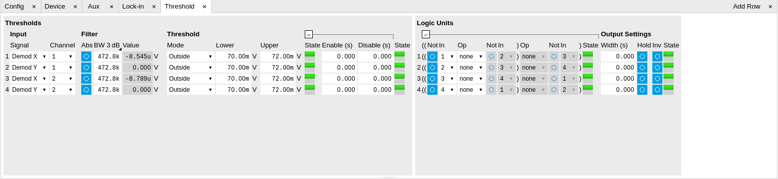
The available input signals include analog signals such as demodulator R, but also digital inputs or error flags of the instrument such as Signal Input overload. An analog input signal can be low-pass filtered which helps to avoid false alarms when short glitches occur. After filtering the signal is discretized by comparing it to a user-defined threshold or range. Configurable minimum activation times after crossing a threshold allow further tuning of the time-domain behavior. The filtered threshold signal can be displayed in the Scope Tab which helps in defining meaningful threshold conditions. When digital signals are selected as inputs, the activation and deactivation times can be set the same way as for the analog signals. The figures below illustrate and detail the signal processing in the Threshold Unit using flow diagrams and signal graphs.
In order to output these signals on the Trigger outputs, the DIO Tab Mode setting needs to be set to Threshold units, and the Trigger output Drive needs to be enabled. By default, the four logical signals are routed as is to the four Trigger outputs. To set up more complex state detection, up to three input signals can be combined on one output using logical operations. The configuration of the logical operations in the Logic units section is collapsed by default. Base logical operators (AND, OR, XOR) as well as logical inversion (NOT) are available and grouping of the operations is indicated by brackets in the user interface.


Functional Elements
| Control/Tool | Option/Range | Description |
|---|---|---|
| Signal | Select the signal source to be used in the threshold unit. | |
| X | Select the demodulator X component as input. | |
| Y | Select the demodulator Y component as input. | |
| R | Select the demodulator magnitude component as input. | |
| Θ | Select the demodulator phase component as input. | |
| PID Out | Use the PID controller's output signal as input. This needs the PID option to be installed. | |
| PID Shift | Use the PID controller's shift signal. This needs the PID option to be installed. | |
| PID Error | Use the PID controller's error as input. This needs the PID option to be installed. | |
| DIO | Select one of the DIO channels as input. | |
| Trigger In | Select a trigger input as input. | |
| Trigger Out | Select a trigger output as input. | |
| Input Overload (V) | Use voltage input overload as input. | |
| Input Overload (I) | Use current input overload as input. | |
| Output Overload | Use signal output overload as input. | |
| Aux Input Overload | Use aux input overload as input. | |
| Aux Output Overload | Use aux output overload as input. | |
| PID Output Overload | Use PID output overload as input. | |
| TU Output Value | Use TU output value as input. | |
| Channel | index | Select the channel according to the selected signal source. |
| Abs | ON / OFF | Takes the absolute value of an analog input signal. |
| TC/BW Value | numeric value | Defines the characteristic time constant of a low-pass filter applied to an analog input signal. |
| Value | numeric value | Shows the value after the low-pass filter. |
| Source Value Lower Saturation Status | Indicates whether the source saturates at the lower bound. | |
| Off | The source value does not saturate at the lower bound. | |
| On | The source value saturates at the lower bound. | |
| Source Value Upper Saturation Status | Indicates whether the source saturates at the upper bound. | |
| Off | The source value does not saturate at the upper bound. | |
| On | The source value saturates at the upper bound. | |
| Mode | Selects the analysis mode defining the output signal. | |
| Above | Enable if the Signal is above Upper Threshold. | |
| Below | Enable if the Signal is below Lower Threshold. | |
| Outside | Enable if the Signal is outside the range [Lower Threshold, Upper Threshold]. | |
| Rising Edge | Enable if the Signal crosses Upper Threshold from below Lower Threshold. The difference between Upper an Lower Threshold defines the threshold hysteresis. | |
| Falling Edge | Enable if the Signal crosses Lower Threshold from above Upper Threshold. The difference between Upper an Lower Threshold defines the threshold hysteresis. | |
| Lower | numeric value | Lower threshold used to generate the output. In Rising Edge mode, this parameter defines the hysteretic behavior as the output state is reset only when the signal crosses Lower Threshold from above. |
| Upper | numeric value | Upper threshold used to generate the output. In Falling Edge mode, this parameter defines the hysteretic behavior as the output state is reset only when the signal crosses Upper Threshold from below. |
| State | low / high / toggling | Indicates the current output of the threshold unit before the Minimum Time analysis. |
| Enable | numeric value | Minimum duration of threshold violation needed before the output is activated. This can be used as a glitch filter. |
| Disable | numeric value | Minimum duration of threshold compliance needed before the output is deactivated. |
| State | low / high / toggling | Indicates the current output of the threshold after the Minimum Time analysis. |
| Not | ON / OFF | Inverts the input signal. |
| In | index | Selects threshold channel to be used as input. |
| Op | Logical operation applied to the signals to the left and right of the control. | |
| none | No logical operation selected. No additional signals will be used to generate the output. | |
| AND | Use a logical AND operation. | |
| OR | Use a logical OR operation. | |
| XOR | Use a logical XOR operation. | |
| State | low / high / toggling | Indicates the current output of the threshold after the logical combination. |
| Width | numeric value | Select a minimum pulse width for the generated output signal. The width of pulses shorter than this time will be extended. |
| Hold | ON / OFF | Hold the output state indefinitely once it has changed to the activated state. |
| Inv | ON / OFF | Changes the output signal to low-active. |
| State | low / high / toggling | Final output state. |