Multi Device Sync Tab
The Multi Device Sync (MDS) tab gives access to the automatic timing synchronization of measurement data from multiple MF instruments. This functionality and tab is available on all MF instruments.
Features
- Automatic timing synchronization across instruments
- Periodic check of synchronization
- Selectable instrument subgroup
- Status display
Description
The Multi Device Sync tab contains the controls and status information for synchronized measurements on multiple instruments. Whenever the tab is closed or an additional one of the same type is needed, clicking the following icon will open a new instance of the tab.
| Control/Tool | Option/Range | Description |
|---|---|---|
| MDS | Synchronize multiple instruments. |
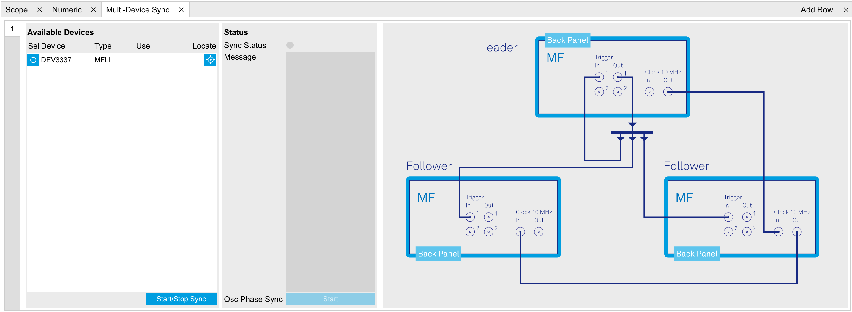
The Multi Device Sync tab shown in Figure 1 consists of the Available Devices section, a Status section, and a wiring diagram.
The Multi Device Synchronization feature provides an automated functionality to remove the clock offset of separate MF instruments. This enables a correct simultaneous display of their data in the Plotter Tab and helps when analyzing recorded data. In multi-channel applications that require sub-microsecond timing precision, the user can therefore benefit from having synchronized data from the start, rather than having to manually measure and compensate the clock offset in post-processing.
The first prerequisite for automatic synchronization is that all instruments are connected to the same LabOne Data Server (see LabOne Software Start-up). This is only possible when running the LabOne software on a separate PC as explained in Running LabOne on a Separate PC.
To make these connections, click on  in the
Config Tab
to open the Device Connection dialog. Go to the Advanced view of this
dialog and click on the Enable checkbox next to the corresponding
entries in the Available Devices list. Once all instruments are
connected, they are selectable in the Tree
Selector
of a newly opened Plotter tab allowing you to visualize their data
simultaneously, though by default these data are not synchronized yet.
The settings of multiple instruments can be accessed in parallel by
opening a new Web Server session for each of them. This is done by
opening a new browser tab and connecting to
in the
Config Tab
to open the Device Connection dialog. Go to the Advanced view of this
dialog and click on the Enable checkbox next to the corresponding
entries in the Available Devices list. Once all instruments are
connected, they are selectable in the Tree
Selector
of a newly opened Plotter tab allowing you to visualize their data
simultaneously, though by default these data are not synchronized yet.
The settings of multiple instruments can be accessed in parallel by
opening a new Web Server session for each of them. This is done by
opening a new browser tab and connecting to localhost:8006 or
127.0.0.1:8006, respectively, and then double-clicking the respective
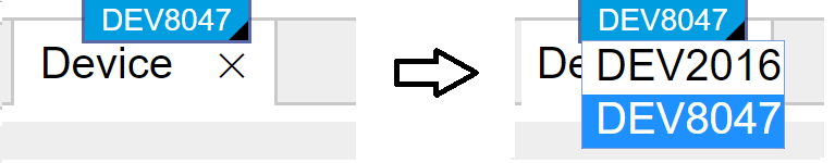
instrument entry in the Available Devices list. With multiple
instruments connected to the same Data Server, tabs that are available
for several instruments will feature a device selector as shown in
Figure 2.
The second prerequisite for automatic synchronization is correct cabling of the instruments explained in the diagram in Figure 3. The instruments should share the same 10 MHz reference clock and communicate via the Ref / Trigger connectors for absolute timing synchronization. The 10 MHz clock signal is distributed in a daisy chain arrangement, where Clock 10 MHz Out of a leading instrument is connected to Clock 10 MHz In of the next instrument, and so forth. On all following instruments, the Clock Source in the Device Tab needs to be set to Clk 10 MHz rather than Internal. The Trigger Out 1 signal of the leading instrument should be distributed to the Trigger In 1 connector of all following instruments and of the leading instrument. This star-shaped connection should be made with a 1-to-N power divider and cables of equal length.

Once the cabling and the connectivity is set up correctly, automatic
synchronization is started in the Multi Device Sync tab by checking the
Enable button on the instruments in the Available Devices list, and then
clicking on  .
The sequence assignment of the instruments (Leader, Follower 1, Follower
2,...) can be defined by the order in which the Enable button is clicked.
This assignment has to agree with the way the cabling is made. The
Message display on the right will then report on the progress, and the
Sync Status LED will turn green if the synchronization was successful.
In that case, visualizing a time-dependent measurement of multiple
instruments in the Plotter will demonstrate the timing synchronization.
.
The sequence assignment of the instruments (Leader, Follower 1, Follower
2,...) can be defined by the order in which the Enable button is clicked.
This assignment has to agree with the way the cabling is made. The
Message display on the right will then report on the progress, and the
Sync Status LED will turn green if the synchronization was successful.
In that case, visualizing a time-dependent measurement of multiple
instruments in the Plotter will demonstrate the timing synchronization.
Functional Elements
| Control/Tool | Option/Range | Description |
|---|---|---|
| Start Sync | |
Start the automatic synchronization of the selected devices. |
| Filter Device Family | Only devices of the same family can be synchronized. Filter the device list based on device family. | |
| Sync Status | Indicates the status of the synchronization within this group. Green: synchronization successful. Yellow: synchronization in progress. Red: error (see message). | |
| Message | Displays a status message of the synchronization group. | |
| Cabling | This image shows how to connect the devices for device synchronization. | |
| Phase Synchronization | Reset phases of all oscillators on all synchronized devices. | |
| Identify Device |  |
Make device's front LED blink |