Pump Tone Cancellation
Note
This tutorial is applicable to all SHFPPC Instruments.
Goals and Requirements
The goal of this tutorial is to demonstrate how to use the SHFPPC and SHFQA or SHFQC via the LabOne Graphical User Interface (GUI) to cancel out pump tone leakage in the readout signal when using quantum-limited parametric amplifiers. The SHFPPC is used to generate a pump tone signal to drive the quantum-limited parametric amplifier and a cancellation tone signal to cancel out the pump tone leakage. The SHFQA or SHFQC QA channel is used to generate and acquire the readout signal.
LabOne Q is the recommended control software to operate the SHFPPC and other instruments for Quantum Technology applications.
Preparation
Connect the cables as illustrated in Figure 1. The trigger signal connection is required only when using the SHFPPC Sweeper.
Make sure that the instruments are powered on, warmed up, and connected by Ethernet to your local area network (recommended) where the host computer resides, or by USB cable directly to your host computer. After starting LabOne, the default web browser opens with the LabOne Graphical User Interface.

Tutorial
In this tutorial, the Pump Output of the SHFPPC channel 1 is used to generate a pump signal, and the Signal Output and Input of the SHFQA channel 1 is used to generate and acquire a readout signal. Although the readout signal generation is not required for the measurement, it is used for the convenience of further experiments. The readout signal at the Signal Input of the SHFPPC is amplified, and combined with a cancellation tone, which is derived from the pump signal through a phase shifter and an attenuator, and then routed to the Signal Output of the SHFPPC, see the SHFPPC Functional Overview.
For simplicity, no qubit system is used in the tutorial, so the Signal Output of the SHFQA channel 1 is connected to the Signal Input of the SHFPPC channel 1. The SHFQA generates a readout signal only with no "pump tone leakage" signal, therefore the acquired signal only shows the readout signal and the cancellation tone signal. By routing an attenuated (<= -40 dB) signal from the Pump Output to the Signal Input of the SHFPPC one could simulate a “pump tone leakage” signal to check the residual pump tone signal.
In case of using the SHFPPC without using the SHFQA or SHFQC, the SHFPPC can be used to generate both pump and probe tone signals on the Pump Output port simultaneously.
The following steps show how to use LabOne GUI to manually perform pump tone cancellation.
-
Configure the SHFPPC channel 1
Configure the Input and Output Tab as in Figure 2 and in Table 1, to send a continuous pump signal with a frequency of 6 GHz and a power of 0 dBm on the Pump Output of the SHFPPC channel 1.
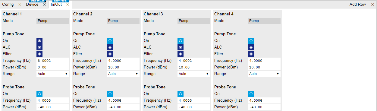
Figure 2: Configurations of the SHFPPC In/Out Tab. Table 1: Settings of Channel 1 on In/Out Tab Parameter Setting Description Pump Tone On Enabled Enables Pump output. ALC Enabled Enables Automatic Level Control (ALC). Filter Enabled Enables low-pass filter. Frequency (Hz) 6 GHz Sets Pump output frequency. Power (dBm) 0 dBm Sets Pump output power. Probe Tone On Disabled Disables Probe Tone Output. Configure the Cancellation Tab as in Figure 3 and Table 2, to generate a cancellation tone.
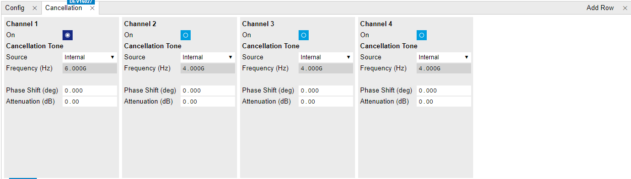
Figure 3: Configurations of the SHFPPC Cancellation Tab. Table 2: Settings on Cancellation Tab Parameter Setting Description Cancellation Tone On Enabled Enables cancellation output. Source Internal Sets cancellation tone generation to internal, so the cancellation tone is generated from the pump signal on the same channel through a phase shifter and an attenuator. If the cancellation tone is generated externally, set the Source to "External" and enter the cancellation frequency for phase shift calculation. Phase Shift (deg) 0 Sets phase shift of the phase shifter on the cancellation path. Attenuation (dB) 0 Sets attenuation of the attenuator on the cancellation path. -
Configure the SHFQA channel 1.
Configure the Input and Output Tab, the QA Setup Tab, and the Scope Tab as shown in the Figures below, to generate a continuous readout waveform with a frequency of 5.01 GHz and a power of -16 dBm on the Signal Output of SHFQA channel 1, and to monitor the input signal on the Signal Input of SHFQA channel 1. The generated readout signal is sent to the Signal Input of the SHFPPC to be amplified by about 10 dB and combined with a part of the pump signal with tunable phase and attenuation. Finally, the combined signal is sent through the Signal Output of the SHFPPC and the Signal Input of the SHFQA, and monitored by the SHFQA Scope.
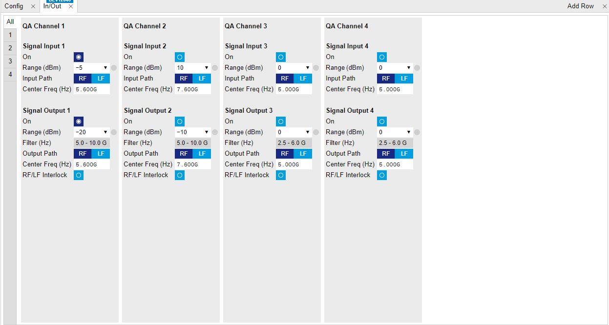
Figure 4: Configurations of the SHFQA In/Out Tab. 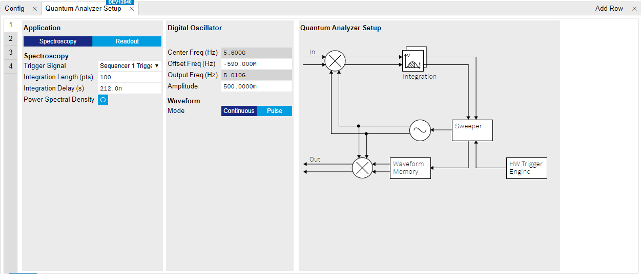
Figure 5: Configurations of the SHFQA Quantum Analyzer Setup Tab. 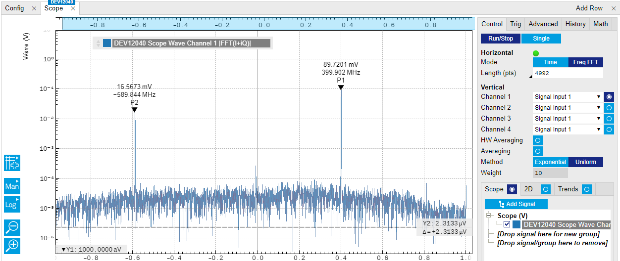
Figure 6: Configurations of the SHFQA Scope Tab. Table 3: Settings of QA Channel 1 on In/Out Tab, QA Setup Tab, and Scope Tab. Parameter Setting Description In/Out Tab Signal Input On Enabled Enables Signal Input. Signal Input Power Range (dBm) -5 dBm Sets signal input power range to -5 dBm. Input Path RF Sets signal input path to RF path. Input Center Freq (Hz) 5.6 GHz Sets signal input center frequency to 5.6 GHz. Signal Output On Enabled Enable Signal Output. Signal Output Power Range -20 dBm Sets signal output power range to -20 dBm. Output Path RF Sets signal output path to RF path. Signal Output Center Freq (Hz) 5.6 GHz Sets signal output center frequency to 5.6 GHz. The center frequencies of signal input and output are the same if configured the input and output paths are the same. Quantum Analyzer Setup Tab Application Mode Spectroscopy Sets application mode to Spectroscopy. Power Spectral Density Disabled Disables the Power Spectral Density measurement mode. Offset Freq (Hz) -590 MHz Sets frequency of the digital oscillator to generate readout signal at 5.01 GHz. This frequency is slightly out of the instrument instantaneous bandwidth, so the output power is slight lower. Amplitude 0.5 Sets dimensionless amplitude of the digital oscillator. Waveform Mode Continuous Sets waveform mode to continuous, so the instrument generates continuous waveform on the output. Scope Tab Run/Stop Enabled Runs the Scope. Horizontal Mode Freq FFT Sets horizontal mode to FFT. Vertical Channel 1 Select Signal Input 1 Selects Signal Input 1 on Scope channel 1 to monitor the input signal. Vertical Channel 1 On Enabled Enables Scope channel 1. Remains the rest of the Scope channels Disabled. HW Averaging Disabled Disables the hardware averaging. Averaging Filter Disabled Disables averaging filter. Scope Display On Selects Scope display. Scope Math Added peak position search Adds measurement tool to search peak positions of the monitored data. -
Manually minimizing the residual pump tone signal
By manually sweeping the phase shift and attenuation of the cancellation tone generated by the SHFPPC, the residual pump tone signal monitored by the SHFQA Scope can be minimized. Since no pump tone leakage is present in the readout signal, only the cancellation tone signal and readout signal are shown on the SHFQA Scope. Please refer to the tutorial Power Spectrum Density Measurement if measurement with averaging is required.