Functional Overview
This chapter provides the overview of the features provided by the SHFPPC Instrument. The first section contains the description of the functional diagram and the hardware and software feature list. The next section details the front panel and the back panel of the instrument. The following section provides product selection and ordering support.
Features
The SHFPPC Instrument consists of two or four groups of channels for operating parametric amplifiers. Each group of channels consists of Pump/Probe Tone Generation and a Readout Signal Conditioning unit processing analog signals (dark blue color), and an SHFPPC Sweeper unit that controls all tunable parameters (light blue color). Here, the Pump/Probe Tone Generation unit generates both pump and probe tones for the control and characterization of Josephson parametric amplifiers, while the Readout Signal Conditioning unit consists of an amplification stage for the measurement readout signal as well as an interferometric pump tone cancellation circuit. The interface units that connect to the front panel are depicted on the left-hand side and the units at the back panel are depicted on the right-hand side of the Figure. Arrows between the panels and the interface units indicate selected physical connections and data flow.

Pump Tone Generation
- Low-noise pump tone outputs, recommended frequency range 4 - 12 GHz
- Calibrated output power, up to 20 dBm
- Integrated probe tone, recommended frequency range 4 - 8.5 GHz, combined with pump tone on a single output
Readout Signal Conditioning
- Low-noise readout signal amplification stage with 10 dB amplification, recommended frequency range 5 - 9 GHz
- Interferometric pump tone cancellation, recommended frequency range 5 - 10 GHz
High-speed Connectivity
- LAN/Ethernet 1 Gbit/s controller interface
- USB 2.0 controller interface
Software
- Zurich Instruments LabOne Q, software for high-level programming of quantum computing experiments (recommended).
- LabOne Graphical User Interface
- LabOne Application Programming Interface
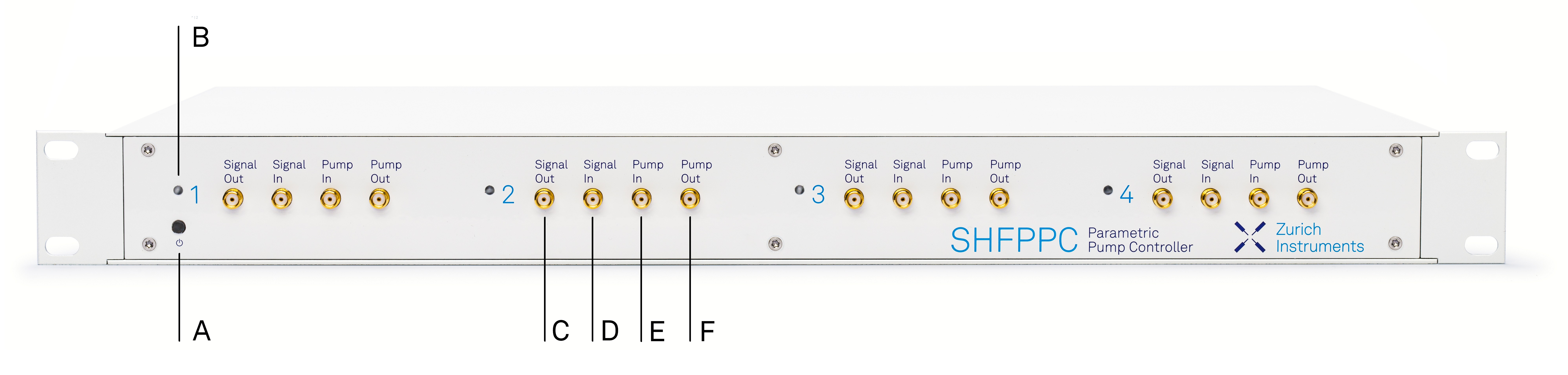
Front Panel Tour
The front panel SMA connectors and control LEDs are arranged as shown in Figure 2 and listed in Table 1.
| Position | Label / Name | Description |
|---|---|---|
| A |  Soft power button |
Power button with incorporated status LED
|
| B | Channel LED | Status indication for Parametric Pump Channel
|
| C | Signal Out | Readout signal output |
| D | Signal In | Readout signal input |
| E | Pump In | External pump tone input |
| F | Pump Out | Parametric Pump Output |
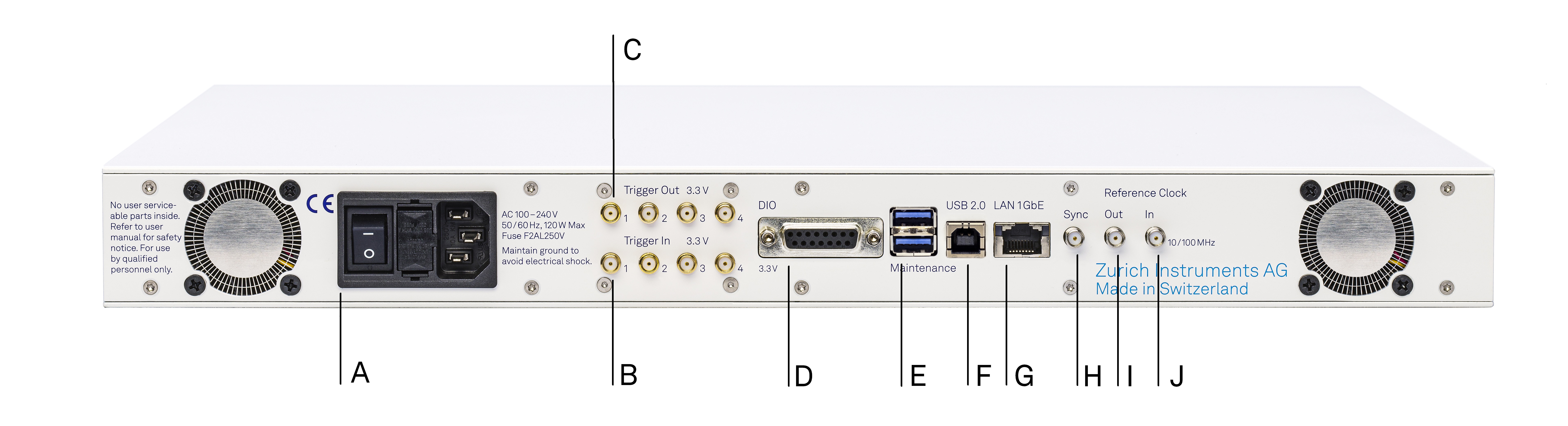
Back Panel Tour
The back panel is the main interface for power, control, service and connectivity to other ZI instruments. Please refer to Figure 3 and Table 2 for the detailed description of the items.
| Position | Label / Name | Description |
|---|---|---|
| A | AC 100 - 240 V | Power inlet, fuse holder, and power switch |
| B | Trigger In | SMA: unidirectional CMOS/TTL ports for trigger input, 3.3 V |
| C | Trigger Out | SMA: unidirectional CMOS/TTL ports for trigger output, 3.3 V |
| D | DIO | 16-bit digital input/output (DIO) connector |
| E | Maintenance | Universal Serial Bus (USB) ports for maintenance → do not use for standard operation |
| F | USB 2.0 | Universal Serial Bus (USB) port for instrument control |
| G | LAN 1GbE | 1 Gbit LAN connector for instrument control |
| H | Sync | Sync Input; no user functionality |
| I | Reference Clock Out | External Reference Clock Output (10 MHz/100 MHz) |
| J | Reference Clock In | External Reference Clock Input (10 MHz/100 MHz) |
Ordering Guide
Table 3 provides an overview of the available SHFPPC products and options.
| Product code | Product name | Description | Field upgrade possible |
|---|---|---|---|
| SHFPPC2 | SHFPPC Parametric Pump Controller 2-Channel Configuration | Base instrument with 2 PPC channels | no |
| SHFPPC4 | SHFPPC Parametric Pump Controller 4-Channel Configuration | Base instrument with 4 PPC channels | no |
| Channel | Feature | SHFPPC2 | SHFPPC4 |
|---|---|---|---|
| Parametric Pump | Readout Channels | 2 | 4 |
| Synthesizers | 2 | 4 | |
| Frequency range | recommended: 4-12 GHz | ||
| Shared resources | Total number of Markers/Triggers | 4/4 | |
| ZSync capability | no | ||
| USB 2.0 | yes | ||
| LAN 1 Gbit/s | yes | ||