Functional Overview
This chapter provides the overview of the features of the MFLI Instrument. The first section contains the graphical overview as well as the hardware and software feature list. The next sections detail the front panel and the back panel of the measurement instrument. The last section provides product selection and ordering support.
Features

Every MF Instrument (MFLI, MFIA) described on Figure 1 consists of several internal units (light blue color) surrounded by several interface units (dark blue color) and the front panel on the left-hand side and the back panel on the right-hand side. The orange blocks are optional units that can be either ordered at the beginning or upgraded later in the field. The arrows between the panels and the interface units indicate the physical connections and the data direction flow. Only a small subset of internal connections is depicted.
The signal of interest is connected to the low-noise current or to the voltage input of the MF Instrument, where it is amplified to a defined range and digitized at very high speed. When the MF-MD option is installed, both inputs can be used simultaneously, enabling 4-terminal measurements for example. The resulting samples are fed into the digital signal processor consisting of up to 4 dual-phase demodulators. The demodulator output samples are further processed on the embedded processor that provides the LabOne web server, to which the user can connect from any device running a browser (PC, tablet or smart phone). No software installation is required. Both Ethernet and USB are supported. The demodulator samples are also available as analog signal on the auxiliary outputs on the front panel of the MF Instrument.
The numerical oscillators generate sine and cosine signal pairs that are used for the demodulation of the input samples and also for the generation of the MF output signals. When the MF-MD option is installed, the Output Adder can generate a linear combination of the oscillator outputs to generate a multi-frequency output signal: digital to analog conversion and signal scaling (range) are supported.
Hardware trigger and reference signals are used for various purposes inside the instrument, such as triggering demodulation, triggering oscilloscope data acquisition, or to generate external reference clocks or triggering signals to other equipment.
Lock-in Operating Modes
- Internal reference mode
- External reference mode
- Auto reference mode
- Impedance mode, measuring current input and voltage input simultaneously (optional)
- Multi-harmonic mode (optional, simultaneous measurement up to four harmonic frequencies)
- Arbitrary frequency mode (optional, simultaneous measurement at 4 arbitrary frequencies)
Medium Frequency Voltage Input
- 1 low-noise MF voltage input, single-ended or differential, 5 MHz bandwidth
- Variable input range
- Switchable input impedance
- Selectable AC/DC coupling
- Selectable instrument ground or floating
Medium Frequency Current Input
- 1 low-noise MF current input, single-ended, 5 MHz bandwidth
- Variable input range
Medium Frequency Signal Output
- Low-distortion MF outputs, single-ended, differential, 5 MHz bandwidth
- Variable output range
- Digital and analog offset
Demodulators & Reference
- Up to 4 dual-phase demodulators
- Up to 4 programmable numerical oscillators
- Up to 2 external reference signals
- Individually programmable demodulator filters
- 128-bit internal processing
- 64-bit resolution demodulator sample
- 48-bit internal reference resolution
Auxiliary Input, Outputs and Triggers
- 4 auxiliary outputs, user defined signals
- 2 auxiliary inputs, general purpose
- 2 input and 2 output trigger signals
High-speed Connectivity
- USB 2.0 Device high-speed 480 Mbit/s interface
- Dual USB 2.0 Host high-speed interface
- LAN 1 Gbit/s controller interface
- DIO: 32-bit digital input-output port
- Clock input connector (10 MHz)
- Clock output connector (10 MHz)
LabOne Toolset
- Sweeper
- Scope
- Numeric
- Spectrum
- Plotter
- Data Acquisition
Software Connectivity
- Data server with multi-client support
- API for C, LabVIEW, MATLAB, Python based instrument programming
Front Panel Tour
The front panel BNC connectors and control LEDs are arranged as shown in Figure 2 and listed in Table 1.
Note
Figure 2 shows the front panel of MF Instruments with serial numbers MF-DEV3200 and higher (see Inspect the Package Contents). On Instruments with smaller serial numbers, the +V and -V Diff connectors (C* and D*) are swapped and the spacing of several connectors is different.

| Position | Label / Name | Description |
|---|---|---|
| A | Signal Input I | single-ended current input |
| B | Current Input Signal Over | this red LED indicates that the current input signal saturates the A/D converter and therefore the current input range must be increased or the signal must be attenuated |
| C* (serial above 3200) | Signal Input –V Diff | voltage input |
| single-ended mode: internally shorted to ground | ||
| differential mode: negative voltage input | ||
| D* (serial above 3200) | Signal Input +V | voltage input |
| in single-ended mode: single-ended voltage input | ||
| differential mode: positive voltage input | ||
| C* (serial below 3200) | Signal Input +V | voltage input |
| single-ended mode: single-ended voltage input | ||
| differential mode: positive voltage input | ||
| D* (serial below 3200) | Signal Input –V Diff | voltage input |
| single-ended mode: internally shorted to ground | ||
| differential mode: negative voltage input | ||
| E | Voltage Input Signal Over | this red LED indicates that the voltage input signal saturates the A/D converter and therefore the voltage input range must be increased or the signal must be attenuated |
| F | Signal Output +V | voltage output |
| single-ended mode: single-ended voltage output | ||
| differential mode: positive voltage output | ||
| G | Signal Output –V Diff | voltage output |
| single-ended mode: internally shorted to ground | ||
| differential mode: negative voltage output | ||
| H | Signal Output ON | this blue LED indicates that the signal output is actively driven by the instrument |
| I | Aux Input 2 Ref | auxiliary input 2, can be used as external reference input supporting the full bandwidth of the device |
| J | Aux Output 2 | auxiliary output 2, this connector provides a user defined signal, often used to output demodulated samples (X,Y) or (R,THETA) |
| K | Aux Output 4 | auxiliary output 4, this connector provides a user defined signal, often used to output demodulated samples (X,Y) or (R,THETA) |
| L | Power | this LED indicates that the instrument is powered |
| color blue: the device has an active connection to the LabOne data server and is ready for operation | ||
| color green blinking: the firmware is ready, waiting for LabOne data server connection. This process takes around 20 seconds. | ||
| color red: the device is not initialized respectively is performing the internal auto calibration process. | ||
| color purple blinking: a firmware update is in progress | ||
| color purple: the boot process failed | ||
| M | Aux Input 1 Ref | auxiliary input 1, can be used as external reference input supporting the full bandwidth of the instrument; the value of auxiliary input 1 can be added as offset to the signal output |
| N | Aux Output 1 | auxiliary output 1, this connector provides a user-defined signal, often used to output demodulated samples (X,Y) or (R,Θ) |
| O | Aux Output 3 | auxiliary output 3, this connector provides a user-defined signal, often used to output demodulated samples (X,Y) or (R,Θ) |
Please refer to the troubleshooting section for further information regarding the meaning of the Power LED colors.
Back Panel Tour
The back panel is the main interface for power, control, service and connectivity to other ZI instruments. Please refer to Figure 3 and Table 2 for the detailed description of the items.

| Position | Label / Name | Description |
|---|---|---|
| A | DC In | DC external 18 V power supply Disregard the 12 V label on device back panel |
| B | DIO | 32-bit digital input/output connector |
| C | USB 2.0 Host | universal serial bus host connector |
| D | USB 2.0 Device | universal serial bus device connector to computer |
| E | LAN 1GbE | 1 Gbit Ethernet LAN connector |
| F | Trigger In 2 | digital TTL trigger input 2 |
| G | Trigger Out 2 | digital TTL trigger output 2 |
| H | Clk 10 MHz In | clock input (10 MHz) to be used for synchronization from external instruments |
| I | Clk 10 MHz Out | clock output (10 MHz) to be used for synchronization of external instruments |
| J | Earth ground | 4 mm banana jack connector for earth ground, electrically connected to the chassis and the earth pin of the power inlet |
| K | USB 2.0 Host | universal serial bus host connector |
| L | Power inlet | power inlet with ON/OFF switch |
| M | Trigger In 1 | digital TTL trigger input 1 |
| N | Trigger Out 1 | digital TTL trigger output 1 |
| O | Cooling outlet | ventilator (important: keep clear from obstruction) |
Ordering Guide
Table 3 provides an overview of the available MF products. Upgrade options can be purchased at any time without need to send the Instrument to Zurich Instruments.
| Product code | Product name | Description | Upgrade in the field possible |
|---|---|---|---|
| MFLI 500 kHz | MFLI 500 kHz Lock-in Amplifier | base product | - |
| MFLI 5 MHz | MFLI 5 MHz Lock-in Amplifier | bundle | - |
| MF-MD | MF-MD Multi-demodulator | option | yes |
| MF-F5M | MF-F5M Frequency Extension | option | yes |
| MF-DIG | MF-DIG Digitizer | option | yes |
| MF-IA | MF-IA Impedance Analyzer | option (includes MFITF) | yes |
| MFITF | Impedance Test Fixture | accessory (included with the MFIA and MF-IA) | - |
The MF product line consists of the MFLI Lock-in Amplifier series and the MFIA Impedance Analyzer series. The combination MFLI 5 MHz + MF-IA is equivalent to the MFIA 5 MHz product, and the combination MFLI 500 kHz + MF-IA is equivalent to the MFIA 500 kHz product. The following table gives an overview of the features for the most important product configurations.
| Feature | MFLI | MFLI +MF-MD | MFLI +MF-F5M | MFLI +MF-MD +MF-F5M |
|---|---|---|---|---|
| Internal reference mode | yes | yes | yes | yes |
| External reference mode | yes | yes | yes | yes |
| Auto reference mode | yes | yes | yes | yes |
| Impedance mode (independent measurement of voltage and current signal inputs) | - | yes | - | yes |
| Signal generators | 1 | 1 | 1 | 1 |
| Superposed output sinusoids per generator | 1 | up to 4 | 1 | up to 4 |
| Quad-harmonic mode | - | yes | - | yes |
| Multi-frequency mode | - | yes | - | yes |
| Arbitrary frequency mode | - | yes | - | yes |
| Number of demodulators | 1 | 4 | 1 | 4 |
| Simultaneous frequencies | 1 | 4 | 1 | 4 |
| Simultaneous harmonics | 1 | 4 | 1 | 4 |
| External references | 1 | 2 | 1 | 2 |
| Dynamic reserve | 120 dB | 120 dB | 120 dB | 120 dB |
| Frequency range | 500 kHz | 500 kHz | 5 MHz | 5 MHz |
| USB 2.0 480 Mbit/s | yes | yes | yes | yes |
| Ethernet 1 GbE | yes | yes | yes | yes |
Rack Mount
Parts for mounting the MFLI in a 19" rack are available from Zurich Instruments upon request under support@zhinst.com. Rack mount of a single MFLI as well as two MFLI instruments side-by-side is possible and explained in the following instructions.
Instructions for a Single Instrument
| Description | Quantity | Unit |
|---|---|---|
| 19" Corner bracket Magic 2U RAL 9003 | 1 | PCE |
| 19" Adapter Plate 2U RAL 9003 | 1 | PCE |
| Pan head screw M6 x 16 ISO 14583 A2 T30 | 4 | PCE |
| DIN 125 A 6.4 st. zinc plated washer | 4 | PCE |
| Cage nut KM 6 | 4 | PCE |
| Screw ISO 7380, M4x12, Torx, zinc plated | 2 | PCE |
| Washer DIN 9021 Ø 4.3 zinc plated | 2 | PCE |
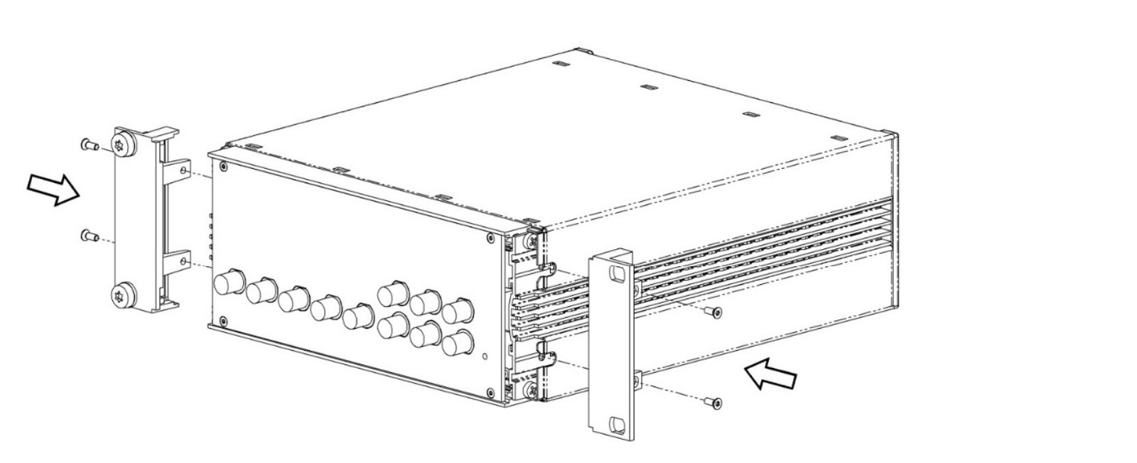
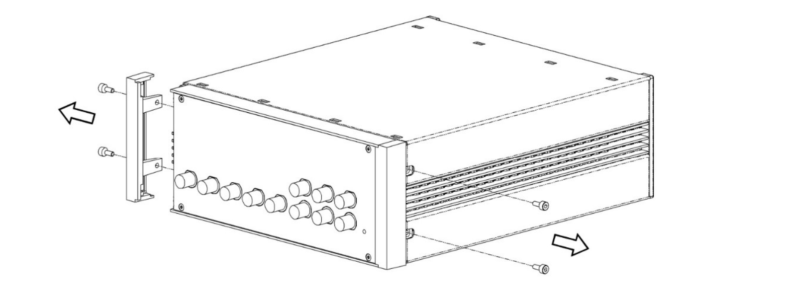
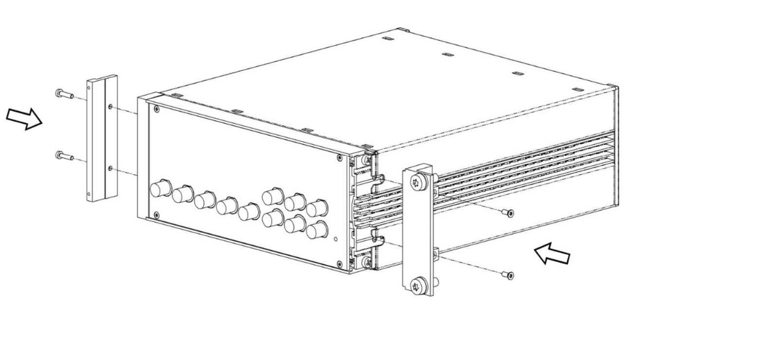
-
Remove 4x screws M3x7
-
Remove 2x trim piece

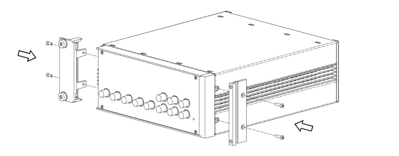
-
Attach 2x 19" Corner bracket Magic 2U RAL 9003 using the screws which were removed in step 1
-
Attach 19"Adapter plate 2U RAL 9003 using 2x screw ISO 7380 M4x12 Torx and washer DIN 9021 Ø 4.3

-
Attach 4x washer DIN 125 A 6.4 and 4x screw ISO 14583 M6x16 Torx for rack mount
-
Attach 4x cage nuts KM6 to cabinet
-
Attach instrument to cabinet
Instructions for Two Instruments
| Description | Quantity | Unit |
|---|---|---|
| Connection Strap Magic 2U outside | 1 | PCE |
| Connection Strap Magic 2U inside | 1 | PCE |
| 19" Corner bracket Magic 2U RAL 9003 | 2 | PCE |
| Connection Strap Magic 2U backside | 1 | PCE |
| Screw sim. DIN 965 M2.5x10 A2 Torx lock | 2 | PCE |
| Screw sim. DIN 7985 M3x12 Torx A2 w. lock-tight | 2 | PCE |
| Pan head screw M6 x 16 ISO 14583 A2 T30 | 4 | PCE |
| DIN 125 A 6.4 st. zinc plated washer | 4 | PCE |
| Cage nut KM 6 | 4 | PCE |
Assembly Instructions: Left Chassis
-
Remove 2x screws M3x7 on the left side and remove left trim piece
-
Remove 2x screws M3x7 on the right side
-
Attach 19" Corner bracket Magic 2U RAL 9003 to the left side with 2x screw M3x7 removed in step 1
-
Attach Connection Strap Magic 2U outside to the right side with 2x DIN 7985 screw M3x12 Torx
Assembly Instructions: Right Chassis
-
Remove 2x screws M3x7 on the right side and remove right trim piece
-
Remove 2x screws M3x7 left side

-
Attach 19" Corner bracket Magic 2U RAL 9003 to the right side with 2x screw M3x7 removed in step 1
-
Attach Connection Strap Magic 2U inside to left the side with screw Cylinder head screw M3x12 Torx
Chassis Assembly
-
Attach both chassis together and fix with 2 screws DIN 965 M2.5x10 Torx through the connection strap
-
Remove 4x screws and 2x inner plastic covers
-
Attach the rear connection strap, using screws removed in step 2
-
Attach Cage nuts KM6 to cabinet