设备节点树
本章包含 MFLI 仪器上可用的设置和测量数据的参考文献。 LabOne 用户界面功能说明 在 LabOne 用户界面的可用功能方面介绍了其中的许多设置,而本章则从设备层面进行介绍,并提供一个按层级组织的设备功能综合列表。
由于这些设置和数据流可使用 LabOne API(应用程序编程接口)来写入和读取,因此用户如果希望通过 LabVIEW、Python、MATLAB、.NET 或 C 语言以编程方式执行测量,应该尤其关注本章的内容。
请参见:
简介 介绍仪器的设置和测量数据在数据服务器的“节点树”中的层级组织方式。参考节点文档 提供按节点树分支整理的 MFLI 仪器上可用设置和测量数据的参考列表。
简介
本章概述仪器的配置和输出在数据服务器中的组织方式。
与仪器进行的所有通信都是通过与仪器连接的数据服务器程序发生的(参见 LabOne 软件架构 获取 LabOne 软件组件的概述)。尽管仪器的设置存储在本地设备上,但数据服务器的任务是确保其保持当前设置的值,并使这些设置(以及任何订阅的数据)可用于所有当前客户端。客户端可以是 LabOne 用户界面,也可以是用户使用某个 LabOne API(例如 Python)执行的自有程序。
仪器的设置和数据由数据服务器以类似文件系统的层级结构来组织,该结构称为节点树。当仪器连接至数据服务器时,其设备 ID 就变为数据服务器节点树内的顶端分支。仪器的各项功能相当于设备顶端分支下面的分支,各种仪器设置相当于这些分支的树叶。
例如,仪器的设备 ID 为“dev2006”,其辅助输出在节点树的分支位置为:
/dev1000/auxouts/
“AUXOUTS”分支下依次是每个辅助输出通道的分支。
/dev1000/auxouts/0/ /dev1000/auxouts/1/ /dev1000/auxouts/2/ /dev1000/auxouts/3/
辅助输出和其他通道在仪器面板和用户界面上使用从 1 开始的索引方式进行标记,但数据服务器的节点树使用的是从 0 开始的索引方式。辅助输出的各个设置(和数据)均作为相应通道的分支下的树叶:
/dev1000/auxouts/0/demodselect /dev1000/auxouts/0/limitlower /dev1000/auxouts/0/limitupper /dev1000/auxouts/0/offset /dev1000/auxouts/0/outputselect /dev1000/auxouts/0/preoffset /dev1000/auxouts/0/scale /dev1000/auxouts/0/value
以上都是节点树中的单个节点路径;最低一级的节点代表单个仪器设置或数据流。相关仪器特定用户手册的“参考节点文档”部分基于每个节点,明确地定义和记录了节点是仪器设置还是数据流,以及它包含或提供哪种类型的数据。不同的属性和类型详见节点属性和数据类型 的解释。
对于仪器设置,数据服务器客户端通过向数据服务器指定适当的路径和一个值,即一个(路径,值)对,来修改节点的值。当在 LabOne 用户界面中更改仪器的设置后,更改后的节点的路径和值显示在窗口底部的状态栏中。关于这一点的详细信息见探索节点树 。
模块参数
LabOne 核心模块(例如参数扫描仪)也使用类似的树状结构来组织其参数。但请注意,模块节点不会显示在数据服务器的节点树中;这些节点位于在 LabOne 客户端中创建的模块实例本地,且不在客户端之间同步。
节点属性和数据类型
一个节点可具有一个或多个以下属性:
读取
可从节点读取数据。
写入
可向节点写入数据。
设置
节点对应一个可写的仪器配置。这些节点的数据以仪器快照的形式保存,并存储在 LabOne XML 设置文件中。
数据流
节点具有读取属性,通常以用户配置的速率提供仪器数据。该数据通常是更复杂的数据类型,例如解调器数据作为 ZIDemodSample 数据返回。数据流节点的完整列表可在编程手册的“仪器通信”章节中查看。它们的可用性取决于设备类别(例如 MF)和设备上安装的选件集。
节点可包含以下类型的数据:
整数
整数数据。
双
双精度浮点数据。
字符串
字符串阵列。
整数(枚举)
整数数据,但是节点仅允许部分数值。
复合数据类型
例如 ZIDemodSample。这些自定义数据类型的结构中,字段包含仪器输出、时间戳和其他相关仪器设置,例如解调器振荡器频率。有关自定义数据类型的文档参见
探索节点树
参见 LabOne 用户界面
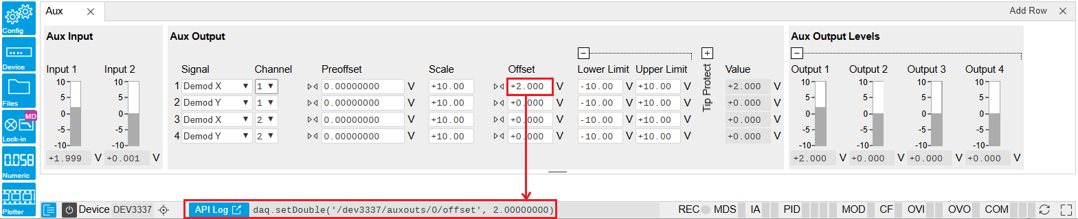
要了解哪个节点负责特定的仪器设置,比较方便的方法之一是在 LabOne 用户界面底部查看 Command Log 历史记录。状态栏中的命令会在每次更改配置后更新。Figure 1 所示为修改辅助输出 1 的偏移值后等效 MATLAB 命令的显示内容。LabOne UI 的命令历史记录的格式可在“Config”(配置)选项卡中进行配置(可选格式包括 Matlab、Python 和 .NET)。
当前 UI 会话中生成的整个历史记录都可通过单击“Show Log”(显示日志)按钮来查看。
Figure 1: 在 LabOne 用户界面中修改设备配置后,状态栏会通过 LabOne 编程界面显示等效命令来执行相同配置。LabOne 编程界面会提供用于修改辅助输出 1 的偏移值的 MATLAB 代码。单击“Show Log”(显示日志)按钮后,整个配置历史记录都会显示在新的浏览器选项卡中。
参见 LabOne 编程界面
使用 listNodes 命令(MATLAB、Python、.NET)或 ziAPIListNodes() 函数 (C API),可从 API 客户端的数据服务器请求(特定分支下的)节点列表。有关使用 listNodes 命令的更多帮助,请参见各 API 的命令参考。为获取从仪器高速提供数据的所有节点(即“数据流节点”)的列表,可向 listNodes 提供 streamingonly 标志。关于数据流和数据流节点的更多信息,请参见 LabOne 编程手册。
参考节点文档 提供的有关节点的详细说明也可通过在 LabOne MATLAB 或 Python 编程界面中使用“help”命令直接访问。help 命令在 Python 和 MATLAB 中分别为 daq.help(path) 和 ziDAQ('help', path)。该命令返回有关仪器节点的描述,包括访问属性、数据类型、单位和可用选件。“help”命令还处理通配符,以返回与路径匹配的所有节点的详细描述。以下为相关示例。
daq = zhinst . core . ziDAQServer ( 'localhost' , 8004 , 6 )
daq . help ( '/dev2006/auxouts/0/offset' )
# Out:
# /dev1000/auxouts/0/offset#
# Add the specified offset voltage to the signal after scaling. Auxiliary Output
# Value = (Signal+Preoffset)*Scale + Offset
# Properties: Read, Write, Setting
# Type: Double
# Unit: V
数据服务器节点
数据服务器在节点树的顶端 /ZI/ 分支下有可用的节点。这些节点提供客户端连接的数据服务器的版本和状态信息。例如,以下节点:
/ZI/ABOUT/VERSION
/ZI/ABOUT/REVISION
为包含数据服务器的发行版本和修订信息的只读节点。/ZI/DEVICES/ 下的节点列出了数据服务器已连接、可发现且可见的设备。
以下节点:
/ZI/CONFIG/OPEN
/ZI/CONFIG/PORT
为设置节点,可用于配置数据服务器从哪个端口监听传入客户端连接,以及它是否可以接受来自本地主机以外主机上的客户端的连接。
对程序员尤其有用的节点是:
/ZI/DEBUG/LOGPATH - 数据服务器日志在电脑文件系统中的位置,
/ZI/DEBUG/LEVEL - 数据服务器当前的日志级别(可配置;具有写入属性),
/ZI/DEBUG/LOG - 作为字符串阵列的最后的数据服务器日志条目。
LabOne 数据服务器的全局节点详列于 LabOne 编程手册的“仪器通信”章节
参考节点文档
本节按分支介绍数据服务器的节点树中的所有节点。
AUXINS
/dev..../auxins/n/averaging
Properties: Read, Write, Setting
Type: Integer (64 bit)
Unit: None
Defines the number of samples on the input to average as a power of two. Possible values are in the range [0, 16]. A value of 0 corresponds to the sampling rate of the auxiliary input's ADC.
/dev..../auxins/n/sample
Properties: Read, Stream
Type: ZIAuxInSample
Unit: V
Voltage measured at the Auxiliary Input after averaging. The data rate depends on the averaging value. Note, if the instrument has demodulator functionality, the auxiliary input values are available as fields in a demodulator sample and are aligned by timestamp with the demodulator output.
/dev..../auxins/n/values/n
Properties: Read
Type: Double
Unit: V
Voltage measured at the Auxiliary Input after averaging. The value of this node is updated at a low rate (50 Hz); the streaming node auxins/n/sample is updated at a high rate defined by the averaging.
AUXOUTS
/dev..../auxouts/n/demodselect
Properties: Read, Write, Setting
Type: Integer (64 bit)
Unit: None
Select the channel number of the selected signal source.
/dev..../auxouts/n/limitlower
Properties: Read, Write, Setting
Type: Double
Unit: V
Lower limit for the signal at the Auxiliary Output. A smaller value will be clipped.
/dev..../auxouts/n/limitupper
Properties: Read, Write, Setting
Type: Double
Unit: V
Upper limit for the signal at the Auxiliary Output. A larger value will be clipped.
/dev..../auxouts/n/max
Properties: Read
Type: Double
Unit: None
Indicates the maximum normalized voltage generated on this channel. It can be between -1 and 1. To prevent signal clipping and overvoltage, it is advised to keep it between -0.9 and 0.9.
/dev..../auxouts/n/min
Properties: Read
Type: Double
Unit: None
Indicates the minimum normalized voltage generated on this channel. It can be between -1 and 1. To prevent signal clipping and overvoltage, it is advised to keep it between -0.9 and 0.9.
/dev..../auxouts/n/offset
Properties: Read, Write, Setting
Type: Double
Unit: V
Add the specified offset voltage to the signal after scaling. Auxiliary Output Value = (Signal+Preoffset)*Scale + Offset
/dev..../auxouts/n/outputselect
Properties: Read, Write, Setting
Type: Integer (enumerated)
Unit: None
Select the signal source to be represented on the Auxiliary Output.
-1
"manual": Select Manual as the output option.
0
"demod_x": Select Demod X as the output option.
1
"demod_y": Select Demod Y as the output option.
2
"demod_r": Select Demod R as the output option.
3
"demod_theta": Select Demod Theta as the output option.
5
"pid": Select PID Out as the output option.
9
"pid_shift": Select PID Shift as the output option.
10
"pid_error": Select PID Error as the output option.
11
"tu_filtered": Select TU Filtered Value as the output option.
13
"tu_output": Select TU Output Value as the output option.
/dev..../auxouts/n/preoffset
Properties: Read, Write, Setting
Type: Double
Unit: Dependent
Add a pre-offset to the signal before scaling is applied. Auxiliary Output Value = (Signal+Preoffset)*Scale + Offset
/dev..../auxouts/n/scale
Properties: Read, Write, Setting
Type: Double
Unit: None
Multiplication factor to scale the signal. Auxiliary Output Value = (Signal+Preoffset)*Scale + Offset
/dev..../auxouts/n/tipprotect/enable
Properties: Read, Write, Setting
Type: Integer (enumerated)
Unit: None
Enable the Tip Protect unit.
0
"off": Switch off the Tip Protect unit.
1
"on": Switch on the Tip Protect unit.
/dev..../auxouts/n/tipprotect/polarity
Properties: Read, Write, Setting
Type: Integer (enumerated)
Unit: None
Select the active level of Source signal.
0
"low": Active when the source signal is at low level.
1
"high": Active when the source signal is at high level.
/dev..../auxouts/n/tipprotect/source
Properties: Read, Write, Setting
Type: Integer (enumerated)
Unit: None
Select the input source for Tip Protect.
0
"tu_output0": Select Threshold Unit 1 as the source signal.
1
"tu_output1": Select Threshold Unit 2 as the source signal.
2
"tu_output2": Select Threshold Unit 3 as the source signal.
3
"tu_output3": Select Threshold Unit 4 as the source signal.
/dev..../auxouts/n/tipprotect/value
Properties: Read, Write, Setting
Type: Double
Unit: V
Signal value written to the Aux Output port when Tip Protect is active. The value overwrites Aux Output Internal value and the Lower and Upper Limits.
/dev..../auxouts/n/value
Properties: Read
Type: Double
Unit: V
Voltage present on the Auxiliary Output. Auxiliary Output Value = (Signal+Preoffset)*Scale + Offset
BOXCARS
/dev..../boxcars/n/averagerbandwidth 
Properties: Read
Type: Double
Unit: Hz
The 3 dB signal bandwidth of the Boxcar Averager is determined by the oscillation frequency and the Number of Averaging Periods set. Note: internally the boxcar signal is sampled at a rate of 14 MSa/s and the signal bandwidth of the auxiliary output is 7 MHz.
/dev..../boxcars/n/baseline/enable
Properties: Read, Write, Setting
Type: Integer (64 bit)
Unit: None
Enable Baseline Suppression.
/dev..../boxcars/n/baseline/windowstart
Properties: Read, Write, Setting
Type: Double
Unit: degree
Boxcar baseline suppression gate opening start in degrees based on one oscillator frequency period equals 360 degrees.
/dev..../boxcars/n/decimation
Properties: Read
Type: Integer (64 bit)
Unit: None
Indicates, in powers of 2, the number of averager outputs sent to the PC while Averaging Periods Boxcar integrations are obtained. Positive integer values indicate oversampling. Negative integer values indicate undersampling. Examples for oversampling values: 0 : 2^0 = 1 averager output is sent to the PC during Averaging Periods Boxcar integrations. 2 : 2^2 = 4 averager outputs are sent to the PC during Averaging Periods Boxcar integrations. -1 : 2^-1 = 0.5, only every other Averaging Periods Boxcar integrations an averager output is sent to the PC.
/dev..../boxcars/n/enable
Properties: Read, Write, Setting
Type: Integer (64 bit)
Unit: Dependent
Enable the BOXCAR unit.
/dev..../boxcars/n/fifooverflow
Properties: Read
Type: Integer (64 bit)
Unit: None
Data lost during streaming to PC. Sticky flag cleared by restarting the boxcar.
/dev..../boxcars/n/inputselect
Properties: Read, Write, Setting
Type: Integer (64 bit)
Unit: V
Select Signal Input used for the boxcar analysis.
/dev..../boxcars/n/limitrate
Properties: Read, Write, Setting
Type: Double
Unit: 1/s
Rate Limit for Boxcar output data sent to PC. This value does not affect the Aux Output for which the effective rate is given by min(14 MSa/s , Frequency / max(1, Averaging Periods/512)).
/dev..../boxcars/n/oscselect
Properties: Read, Write, Setting
Type: Integer (enumerated)
Unit: None
Selection of the oscillator used for the boxcar analysis.
0
Oscillator 1
1
Oscillator 2
2
Oscillator 3
3
Oscillator 4
/dev..../boxcars/n/periodoverflowevents
Properties: Read
Type: Integer (64 bit)
Unit: None
The boxcar averaging gate opening width is more than one cycle of the signal and should be reduced.
/dev..../boxcars/n/periods
Properties: Read, Write, Setting
Type: Integer (64 bit)
Unit: None
Number of periods to average. This setting has no effect on Output PWAs.
/dev..../boxcars/n/rate
Properties: Read
Type: Double
Unit: 1/s
Current data transfer rate to the PC given by min(14 MSa/s , Frequency / max(1, Averaging Periods/512)). This value is read-only.
/dev..../boxcars/n/sample
Properties: Read, Stream
Type: Double
Unit: V
Streaming node containing the output data of the boxcar.
/dev..../boxcars/n/value
Properties: Read
Type: Double
Unit: Dependent
The current boxcar output.
/dev..../boxcars/n/windowsize
Properties: Read, Write, Setting
Type: Double
Unit: s
Boxcar averaging gate opening width in seconds. It can be converted to phase assuming 360 equals to a full period of the driving oscillator.
/dev..../boxcars/n/windowstart
Properties: Read, Write, Setting
Type: Double
Unit: degree
Boxcar averaging gate opening start in degrees. It can be converted to time assuming 360 equals to a full period of the driving oscillator.
CLOCKBASE
/dev..../clockbase
Properties: Read
Type: Double
Unit: Hz
Returns the internal clock frequency of the device.
CURRINS
/dev..../currins/n/autorange
Properties: Read, Write
Type: Integer (64 bit)
Unit: None
Automatic adjustment of the Range to approximately two times the maximum current input amplitude.
/dev..../currins/n/float
Properties: Read, Write, Setting
Type: Integer (enumerated)
Unit: None
Switches the input between floating (ON) and connected grounds (OFF). This setting applies both to the voltage and the current input. It is recommended to discharge the test device before connecting or to enable this setting only after the signal source has been connected to the Signal Input in grounded mode.
0
"off": OFF: GND connected
1
"on": ON: Floating
/dev..../currins/n/max
Properties: Read, Write
Type: Double
Unit: None
Indicates the maximum normalized current measured on this channel. It can be between -1 and 1. To prevent signal clipping and overcurrent, it is advised to keep it between -0.9 and 0.9.
/dev..../currins/n/min
Properties: Read, Write
Type: Double
Unit: None
Indicates the minimum normalized current measured on this channel. It can be between -1 and 1. To prevent signal clipping and overcurrent, it is advised to keep it between -0.9 and 0.9.
/dev..../currins/n/on
Properties: Read, Write, Setting
Type: Integer (64 bit)
Unit: None
Enables the current input.
/dev..../currins/n/range
Properties: Read, Write, Setting
Type: Double
Unit: A
Defines the gain of the current input amplifier. The range should exceed the incoming signal by roughly a factor of two including a potential DC offset. The instrument selects the next higher available range relative to a value inserted by the user. A suitable choice of this setting optimizes the accuracy and signal-to-noise ratio by ensuring that the full dynamic range of the input ADC is used.
/dev..../currins/n/rangestep/trigger
Properties: Read, Write
Type: Integer (64 bit)
Unit: None
Switches to the next appropriate input range such that the range fits best with the measured input current.
/dev..../currins/n/scaling
Properties: Read, Write, Setting
Type: Double
Unit: None
Applies the given scale factor to the current input.
DEMODS
/dev..../demods/n/adcselect
Properties: Read, Write, Setting
Type: Integer (enumerated)
Unit: None
Selects the input signal for the demodulator.
0
"sigin0", "signal_input0": Sig In 1
1
"currin0", "current_input0": Curr In 1
2
"trigin0", "trigger_input0": Trigger Input 1
3
"trigin1", "trigger_input1": Trigger Input 2
4
"auxout0", "auxiliary_output0": Aux Out 1
5
"auxout1", "auxiliary_output1": Aux Out 2
6
"auxout2", "auxiliary_output2": Aux Out 3
7
"auxout3", "auxiliary_output3": Aux Out 4
8
"auxin0", "auxiliary_input0": Aux In 1
9
"auxin1", "auxiliary_input1": Aux In 2
174
"demod_constant_input": Demodulate a constant input. This results in a sine wave of the frequency specified by the demodulator's oscillator with an amplitude of 1 (at lower frequencies; higher frequencies will be attenuated). The maximum possible frequency is limited by the demodulator sampling rate and bandwidth; use demodulator order 1 for the least attenuation in demodulator output. This signal may be used with the auxiliary outputs, PID and Threshold Unit for advanced measurement and control tasks. When the demodulator output is written to an auxiliary output, the resulting signal can also be used as a second output channel (for low frequencies).
/dev..../demods/n/enable
Properties: Read, Write, Setting
Type: Integer (enumerated)
Unit: None
Enables the data acquisition for the corresponding demodulator. Note: increasing number of active demodulators increases load on the physical connection to the host computer.
0
"off": OFF: demodulator inactive
1
"on": ON: demodulator active
/dev..../demods/n/freq
Properties: Read
Type: Double
Unit: Hz
Indicates the frequency used for demodulation and for output generation. The demodulation frequency is calculated as oscillator frequency times the harmonic factor. When the MOD option is used linear combinations of oscillator frequencies including the harmonic factors define the sideband frequencies.
/dev..../demods/n/harmonic
Properties: Read, Write, Setting
Type: Integer (64 bit)
Unit: None
Multiplies the selected oscillator's frequency by an integer. If the demodulator is used as a phase detector in external reference mode (PLL), the effect is that the internal oscillator locks to the external frequency divided by the integer factor.
/dev..../demods/n/order
Properties: Read, Write, Setting
Type: Integer (enumerated)
Unit: None
Selects the filter roll off between 6 dB/oct and 48 dB/oct.
1
1st order filter 6 dB/oct
2
2nd order filter 12 dB/oct
3
3rd order filter 18 dB/oct
4
4th order filter 24 dB/oct
5
5th order filter 30 dB/oct
6
6th order filter 36 dB/oct
7
7th order filter 42 dB/oct
8
8th order filter 48 dB/oct
/dev..../demods/n/oscselect
Properties: Read, Write, Setting
Type: Integer (enumerated)
Unit: None
Assignes an oscillator to the demodulator. Number of available oscillators depends on the installed options.
0
Oscillator 1
1
Oscillator 2
2
Oscillator 3
3
Oscillator 4
/dev..../demods/n/phaseadjust
Properties: Read, Write
Type: Integer (64 bit)
Unit: None
Adjust the demodulator phase automatically in order to read 0 degrees.
/dev..../demods/n/phaseshift
Properties: Read, Write, Setting
Type: Double
Unit: deg
Applies phase shift to the reference input of the demodulator.
/dev..../demods/n/rate
Properties: Read, Write, Setting
Type: Double
Unit: 1/s
Defines the demodulator sampling rate, the number of samples that are sent to the host computer per second. A rate of about 7-10 higher as compared to the filter bandwidth usually provides sufficient aliasing suppression. This is also the rate of data received by LabOne Data Server and saved to the computer hard disk. This setting has no impact on the sample rate on the auxiliary outputs connectors. Note: the value inserted by the user may be approximated to the nearest value supported by the instrument.
/dev..../demods/n/sample
Properties: Read, Stream
Type: ZIDemodSample
Unit: Dependent
Contains streamed demodulator samples with sample interval defined by the demodulator data rate.
/dev..../demods/n/sinc
Properties: Read, Write, Setting
Type: Integer (64 bit)
Unit: None
Enables the sinc filter. When the filter bandwidth is comparable to or larger than the demodulation frequency, the demodulator output may contain frequency components at the frequency of demodulation and its higher harmonics. The sinc is an additional filter that attenuates these unwanted components in the demodulator output.
/dev..../demods/n/timeconstant
Properties: Read, Write, Setting
Type: Double
Unit: s
Sets the integration time constant or in other words, the cutoff frequency of the demodulator low pass filter.
/dev..../demods/n/trigger
Properties: Read, Write, Setting
Type: Integer (enumerated)
Unit: None
Selects the acquisition mode (i.e. triggering) of the demodulator.
0
"continuous": Continuous: demodulator data is continuously streamed to the host computer.
1
"trigin0_rising", "trigger_input0_rising": Trigger Input 1: rising edge triggered.
2
"trigin0_falling", "trigger_input0_falling": Trigger Input 1: falling edge triggered.
3
"trigin0_both", "trigger_input0_both": Trigger Input 1: triggering on both rising and falling edge.
4
"trigin1_rising", "trigger_input1_rising": Trigger Input 2: rising edge triggered.
5
"trigin0or1_rising", "trigger_input0or1_rising": Trigger Input 1 or 2: rising edge triggered on either input.
8
"trigin1_falling", "trigger_input1_falling": Trigger Input 2: falling edge triggered.
10
"trigin0or1_falling", "trigger_input0or1_falling": Trigger Input 1 or 2: falling edge triggered on either input.
12
"trigin1_both", "trigger_input1_both": Trigger Input 2: triggering on both rising and falling edge.
15
"trigin0or1_both", "trigger_input0or1_both": Trigger Input 1 or 2: triggering on both rising and falling edge or either trigger input.
16
"trigin0_low", "trigger_input0_low": Trigger Input 1: demodulator data is streamed to the host computer when the level is low (TTL).
32
"trigin0_high", "trigger_input0_high": Trigger Input 1 for MF: demodulator data is streamed to the host computer when the level is high (TTL).
64
"trigin1_low", "trigger_input1_low": Trigger Input 2: demodulator data is streamed to the host computer when the level is low (TTL).
80
"trigin0or1_low", "trigger_input0or1_low": Trigger Input 1 or 2: demodulator data is streamed to the host computer when either level is low (TTL).
128
"trigin1_high", "trigger_input1_high": Trigger Input 2: demodulator data is streamed to the host computer when the level is high (TTL).
160
"trigin0or1_high", "trigger_input0or1_high": Trigger Input 1 or 2: demodulator data is streamed to the host computer when either level is high (TTL).
DIOS
/dev..../dios/n/auxdrive
Properties: Read
Type: Integer (64 bit)
Unit: None
Not used. Reserved for future use.
/dev..../dios/n/decimation
Properties: Read, Write, Setting
Type: Integer (64 bit)
Unit: None
Sets the decimation factor for DIO data streamed to the host computer.
/dev..../dios/n/drive
Properties: Read, Write, Setting
Type: Integer (64 bit)
Unit: None
When on (1), the corresponding 8-bit bus is in output mode. When off (0), it is in input mode. Bit 0 corresponds to the least significant byte. For example, the value 1 drives the least significant byte, the value 8 drives the most significant byte.
/dev..../dios/n/extclk
Properties: Read, Write, Setting
Type: Integer (enumerated)
Unit: None
Select DIO internal or external clocking.
0
"internal": The DIO is internally clocked with a fixed frequency of 60 MHz.
1
"external": The DIO is externally clocked with a clock signal connected to DIO Pin 68. The available range is from 1 Hz up to the internal clock frequency.
/dev..../dios/n/input
Properties: Read, Stream
Type: ZIDIOSample
Unit: None
Gives the value of the DIO input for those bytes where drive is disabled.
/dev..../dios/n/mode
Properties: Read, Write, Setting
Type: Integer (enumerated)
Unit: None
Select DIO mode
0
"manual": Enables manual control of the DIO output bits.
3
"threshold_unit": Enables setting of DIO output values by the threshold unit.
/dev..../dios/n/output
Properties: Read, Write, Setting
Type: Integer (64 bit)
Unit: None
Sets the value of the DIO output for those bytes where 'drive' is enabled.
EXTREFS
/dev..../extrefs/n/adcselect
Properties: Read
Type: Integer (enumerated)
Unit: None
Indicates the input signal selection for the selected demodulator.
0
"sigin0", "signal_input0": Signal Input 1 is connected to the corresponding demodulator.
1
"currin0", "current_input0": Current Input 1 is connected to the corresponding demodulator.
2
"trigin0", "trigger_input0": Trigger Input 1 is connected to the corresponding demodulator.
3
"trigin1", "trigger_input1": Trigger Input 2 is connected to the corresponding demodulator.
4
"auxout0", "auxiliary_output0": Auxiliary Output 1 is connected to the corresponding demodulator.
5
"auxout1", "auxiliary_output1": Auxiliary Output 2 is connected to the corresponding demodulator.
6
"auxout2", "auxiliary_output2": Auxiliary Output 3 is connected to the corresponding demodulator.
7
"auxout3", "auxiliary_output3": Auxiliary Output 4 is connected to the corresponding demodulator.
8
"auxin0", "auxiliary_input0": Auxiliary Input 1 is connected to the corresponding demodulator.
9
"auxin1", "auxiliary_input1": Auxiliary Input 2 is connected to the corresponding demodulator.
174
"demod_constant_input": Constant is connected to the corresponding demodulator. This results in a sine wave of the frequency specified by the demodulator's oscillator with an amplitude of 1 or lower, depending on frequency and filter settings.
/dev..../extrefs/n/automode
Properties: Read, Write, Setting
Type: Integer (enumerated)
Unit: None
This defines the type of automatic adaptation of parameters in the PID used for Ext Ref.
2
"low_bandwidth", "pid_coeffs_filter_low_bw": The PID coefficients, the filter bandwidth and the output limits are automatically set using a low bandwidth.
3
"high_bandwidth", "pid_coeffs_filter_high_bw": The PID coefficients, the filter bandwidth and the output limits are automatically set using a high bandwidth.
4
"all", "pid_coeffs_filter_auto_bw": The PID coefficient, the filter bandwidth and the output limits are dynamically adapted.
/dev..../extrefs/n/demodselect
Properties: Read, Write, Setting
Type: Integer (64 bit)
Unit: None
Indicates the demodulator connected to the extref channel.
/dev..../extrefs/n/enable
Properties: Read, Write, Setting
Type: Integer (64 bit)
Unit: None
Enables the external reference.
/dev..../extrefs/n/locked
Properties: Read
Type: Integer (64 bit)
Unit: None
Indicates whether the external reference is locked.
/dev..../extrefs/n/oscselect
Properties: Read
Type: Integer (64 bit)
Unit: None
Indicates which oscillator is being locked to the external reference.
FEATURES
/dev..../features/code
Properties: Write
Type: String
Unit: None
Node providing a mechanism to write feature codes.
/dev..../features/devtype
Properties: Read
Type: String
Unit: None
Returns the device type.
/dev..../features/options
Properties: Read
Type: String
Unit: None
Returns enabled options.
/dev..../features/serial
Properties: Read
Type: String
Unit: None
Device serial number.
IMPS
/dev..../imps/n/ac
Properties: Read, Write, Setting
Type: Integer (64 bit)
Unit: None
Defines the input coupling for the Signal Inputs. AC coupling inserts a high-pass filter.
/dev..../imps/n/auto/bw
Properties: Read, Write, Setting
Type: Integer (64 bit)
Unit: None
Enable automatic bandwidth control. If enabled the optimum bandwidth is calculated based on the frequency and measurement data.
/dev..../imps/n/auto/inputrange
Properties: Read, Write, Setting
Type: Integer (enumerated)
Unit: None
Select input range control mode.
0
Manual: In manual mode the current and voltage input ranges are adjusted manually and separately. Use this mode with care as overload will result in inaccurate impedance results.
1
Auto: Dynamically adjust the input range according to the measured input signal strength. This optimizes the dynamic range and precision of impedance measurements.
2
Zone: This ranging option allows you to manually set the switching frequency limits for all eight current input ranges.
/dev..../imps/n/auto/output
Properties: Read, Write, Setting
Type: Integer (64 bit)
Unit: None
If enabled, the drive voltage amplitude is controlled by the device. If disabled it can be set manually.
/dev..../imps/n/auto/suppress
Properties: Read, Write
Type: Integer (64 bit)
Unit: None
Indicates disabled periodic auto range control. A running sweeper module takes over the range control and thus disables the periodic range checks.
/dev..../imps/n/bias/enable
Properties: Read, Write, Setting
Type: Integer (64 bit)
Unit: None
Enables the DC bias voltage.
/dev..../imps/n/bias/value
Properties: Read, Write, Setting
Type: Double
Unit: V
DC bias voltage applied across the device under test. Both positive and negative bias voltages are supported. In a 4-terminal measurement, the bias voltage is limited by the maximum common voltage input range of the device. In a 2-terminal measurement, the bias voltage can be larger because the voltage inputs are not connected.
/dev..../imps/n/calib/internal/active
Properties: Read
Type: Integer (64 bit)
Unit: None
Indicates if the internal calibration is applied to the measurement data.
/dev..../imps/n/calib/internal/enable
Properties: Read, Write, Setting
Type: Integer (64 bit)
Unit: None
Enables the internal calibration. This ensures that the input range gains match over the full frequency range. With enabled internal calibration the device fulfills the impedance accuracy specification. The internal calibration is a prerequisite to apply a user compensation.
/dev..../imps/n/calib/internal/smooth
Properties: Read, Write, Setting
Type: Integer (64 bit)
Unit: None
Enables smoothing of the internal calibration data. This results in lower noise in the measured data.
/dev..../imps/n/calib/user/active
Properties: Read
Type: Integer (64 bit)
Unit: None
Indicates that a valid user compensation is active. If active the impedance data streams deliver amplitude and phase corrected data based on the impedance user compensation.
/dev..../imps/n/calib/user/enable
Properties: Read, Write, Setting
Type: Integer (64 bit)
Unit: None
Enables the user compensation of the impedance data. The user compensation is correcting parasitics and delays caused by the external setup. The user compensation is applied on top of the internal impedance calibration.
/dev..../imps/n/calib/user/smooth
Properties: Read, Write, Setting
Type: Integer (64 bit)
Unit: None
Enables smoothing of the compensation data. This results in lower noise in the measured data.
/dev..../imps/n/confidence/compensation/enable
Properties: Read, Write, Setting
Type: Integer (64 bit)
Unit: None
Enables the indication of strong compensation in the plots. A strong compensation diminishes the measurement accuracy of the parameter.
/dev..../imps/n/confidence/compensation/ratio
Properties: Read, Write, Setting
Type: Double
Unit: None
Strength of the compensation that will trigger the strong compensation warning.
/dev..../imps/n/confidence/enable
Properties: Read, Write, Setting
Type: Integer (64 bit)
Unit: None
Enables/disables all confidence indicators to check the reliability of the measured data. To enable individual indicators, open the advanced tab.
/dev..../imps/n/confidence/freqlimit/enable
Properties: Read, Write, Setting
Type: Integer (64 bit)
Unit: None
Enables the frequency limit detection based on the used current input range. Only relevant when Range Control is set to Manual.
/dev..../imps/n/confidence/lowdut2t/enable
Properties: Read, Write, Setting
Type: Integer (64 bit)
Unit: None
Enables a warning when meassuring a low impedance (100k) with a 2 point contact.
/dev..../imps/n/confidence/lowdut2t/ratio
Properties: Read, Write, Setting
Type: Double
Unit: None
When measuring with 2 point contacts, too low impedance of DUT will trigger the Low DUT 2T warning.
/dev..../imps/n/confidence/oneperiod/enable
Properties: Read, Write, Setting
Type: Integer (64 bit)
Unit: None
Enables the detection of unreliable data points where data sample loss leads to an invalid one-period average. Try reducing the data transfer rate.
/dev..../imps/n/confidence/opendetect/enable
Properties: Read, Write, Setting
Type: Integer (64 bit)
Unit: None
Enables the open terminal detection for 4-terminal measurements.
/dev..../imps/n/confidence/opendetect/ratio
Properties: Read, Write, Setting
Type: Double
Unit: None
Open terminal detection ratio. An open terminal is reported if the excitation calculated from current and voltage drop differs more than the specified factor from the driving voltage.
/dev..../imps/n/confidence/overflow/enable
Properties: Read, Write, Setting
Type: Integer (64 bit)
Unit: None
Enables the overload detection for current and voltage.
/dev..../imps/n/confidence/qfactor/enable
Properties: Read, Write, Setting
Type: Integer (64 bit)
Unit: None
Enables the detection of negative Q or D factors. Negative Q or D factors mean the measured impedance does not correspond to the chosen Representation. This can be due to an erroneous compensation, a bad choice of the Representation, or noise.
/dev..../imps/n/confidence/suppression/enable
Properties: Read, Write, Setting
Type: Integer (64 bit)
Unit: None
The Suppression Confidence Indicator indicates if one of the two parameters of a circuit representation cannot be calculated reliably from the measured impedance. This is the case if a small variation in one (dominant) representation parameter creates a strong variation of the other (suppressed) representation parameter. Such an error amplification indicates that the measurement of the secondary parameter is unreliable.
/dev..../imps/n/confidence/suppression/ratio
Properties: Read, Write, Setting
Type: Double
Unit: None
Error amplification limit for which a secondary parameter is marked unreliable. Larger gain values mean larger warning tolerances. A gain value between 10 and 100 is best.
/dev..../imps/n/confidence/underflow/enable
Properties: Read, Write, Setting
Type: Integer (64 bit)
Unit: None
Enables the underflow detection for current and voltage.
/dev..../imps/n/confidence/underflow/ratio
Properties: Read, Write, Setting
Type: Double
Unit: None
The underflow condition is met if the measured amplitude is lower than the specified ratio relative to full scale.
/dev..../imps/n/current/demodselect
Properties: Read
Type: Integer (64 bit)
Unit: None
Demodulator used for current demodulation.
/dev..../imps/n/current/inputselect
Properties: Read, Write, Setting
Type: Integer (enumerated)
Unit: None
Select the current input used for two- and four-terminal impedance measurements.
0
"currin0", "current_input0": Current Input 1
8
"auxin0", "auxiliary_input0": Aux In 1
9
"auxin1", "auxiliary_input1": Aux In 2
/dev..../imps/n/current/invert
Properties: Read, Write, Setting
Type: Integer (64 bit)
Unit: None
If enabled, the current input signal is inverted. This is useful to switch the polarity of an input signal which can be caused by additional current amplifiers.
/dev..../imps/n/current/pid/enable
Properties: Read, Write, Setting
Type: Integer (64 bit)
Unit: None
If enabled, the PID value is used for the impedance calculation instead of the measured value at the current input.
/dev..../imps/n/current/range
Properties: Read, Write, Setting
Type: Double
Unit: A
Input current range used for the impedance measurement. Small current input ranges have a reduced bandwidth. In the Range Control modes 'Auto' and 'Impedance', the current range is switched automatically to a higher range if the frequency is too high.
/dev..../imps/n/current/scaling
Properties: Read, Write, Setting
Type: Double
Unit: A/V
The scaling factor will be applied to the current measurement done with an Aux In input.
/dev..../imps/n/demod/harmonic
Properties: Read, Write, Setting
Type: Integer (64 bit)
Unit: None
Multiplies the demodulator's reference frequency with the integer factor defined by this field.
/dev..../imps/n/demod/order
Properties: Read, Write, Setting
Type: Integer (enumerated)
Unit: None
Selects the filter roll off between 6 dB/oct and 48 dB/oct of the current demodulator.
1
1st order filter 6 dB/oct
2
2nd order filter 12 dB/oct
3
3rd order filter 18 dB/oct
4
4th order filter 24 dB/oct
5
5th order filter 30 dB/oct
6
6th order filter 36 dB/oct
7
7th order filter 42 dB/oct
8
8th order filter 48 dB/oct
/dev..../imps/n/demod/oscselect
Properties: Read, Write, Setting
Type: Integer (enumerated)
Unit: None
Oscillator used to generate the frequency of the excitation voltage on the Hcur (+V) connector.
0
Oscillator 1
1
Oscillator 2
2
Oscillator 3
3
Oscillator 4
/dev..../imps/n/demod/rate
Properties: Read, Write, Setting
Type: Double
Unit: 1/s
Impedance data streaming rate. The same data rate is applied to the demodulators that are used for the impedance measurement.
/dev..../imps/n/demod/sinc
Properties: Read, Write, Setting
Type: Integer (64 bit)
Unit: None
Enables the sinc filter.
/dev..../imps/n/demod/timeconstant
Properties: Read, Write, Setting
Type: Double
Unit: s
Defines low pass filter time constant.
/dev..../imps/n/discard/enable
Properties: Read, Write, Setting
Type: Integer (64 bit)
Unit: None
Discarding impedance samples outside the indicated range.
/dev..../imps/n/discard/limitlower
Properties: Read, Write, Setting
Type: Double
Unit: None
Threshold for abs(Z) below which the impedance samples are discarded.
/dev..../imps/n/discard/limitupper
Properties: Read, Write, Setting
Type: Double
Unit: None
Threshold for abs(Z) above which the impedance samples are discarded.
/dev..../imps/n/enable
Properties: Read, Write, Setting
Type: Integer (64 bit)
Unit: None
Enable impedance calculation for demodulator data.
/dev..../imps/n/freq
Properties: Read, Write, Setting
Type: Double
Unit: Hz
Frequency control for the oscillator used for impedance measurement.
/dev..../imps/n/interpolation
Properties: Read, Write, Setting
Type: Integer (enumerated)
Unit: None
Select the interpolation method of the compensation data. The interpolation method is particularly important if the derivative changes strongly e.g at cut-off frequencies.
0
"linear": Linear: The linear interpolation is fastest but may create compensation errors in between the frequency points used for compensation.
1
"pchip": Piecewise Cubic Hermite (PCHIP): The piecewise cubic Hermite interpolation will result in very accurate results but requires more calculation power.
/dev..../imps/n/maxbandwidth 
Properties: Read, Write, Setting
Type: Double
Unit: Hz
Limit of the maximum bandwidth used on the demodulator filter. Values above 1 kHz can heavily diminish measurement accuracy in the high-frequency region where the amplitude is no more constant over frequency.
/dev..../imps/n/mode
Properties: Read, Write, Setting
Type: Integer (enumerated)
Unit: None
Select impedance measurement mode.
0
4 Terminal: This method uses the current and the voltage drop across the DUT to calculate the DUT impedance. This method results in very accurate measurements as influences of series resistors on the output and current input are excluded.
1
2 Terminal: This method uses the driving voltage and the measured current to calculate the DUT impedance. The 2 Terminal method can be beneficial when measuring very high impedance where the parasitics of the voltage measurement are limiting the frequency range.
/dev..../imps/n/model
Properties: Read, Write, Setting
Type: Integer (enumerated)
Unit: None
Representation of the complex impedance value Z by two real values accessible as Parameter 1 and Parameter 2 on all user interface displays.
0
"r_c_parallel": Rp || Cp: Impedance value Z is represented by a resistive element Rp in parallel with a capacitive element Cp.
1
"r_c_series": Rs + Cs: Impedance value Z is represented by a resistive element Rs in series with a capacitive element Cs.
2
"r_l_series": Rs + Ls: Impedance value Z is represented by a resistive element Rs in series with an inductive element Ls.
3
"g_b_parallel", "admittance": G B: Impedance value Z is represented by conductance G = Real(Y) and Susceptance B = Imag(Y) of the admittance Y = 1/Z.
4
"d_c_series": D Cs: Impedance value Z is represented by a dissipation factor D = -Real(Z)/Imag(Z) (loss tangent) and a series capacitive element.
5
"q_c_series": Q Cs: Impedance value Z is represented by a quality factor Q = -Imag(Z)/Real(Z) and a series capacitive element.
6
"d_l_series": D Ls: Impedance value Z is represented by a dissipation factor D = Real(Z)/Imag(Z) (loss tangent) and a series inductive element.
7
"q_l_series": Q Ls: Impedance value Z is represented by a quality factor Q = Imag(Z)/Real(Z) and a series inductive element.
8
"r_l_parallel": Rp || Lp: Impedance value Z is represented by a resistive element Rp in parallel with an inductive element Lp.
9
"d_c_parallel": D Cp: Impedance value Z is represented by a dissipation factor D = Real(Z)/Imag(Z) (loss tangent) and a parallel capacitive element Cp.
10
"dielectric": Dielectic: Impedance value Z is represented by an equivalent dieletric material with a complex permittivity.
/dev..../imps/n/mut/area
Properties: Read, Write, Setting
Type: Double
Unit: m²
The area of the MUT. Only relevant when using the dielectric model.
/dev..../imps/n/mut/thickness
Properties: Read, Write, Setting
Type: Double
Unit: m
The thickness of the MUT. Only relevant when using the dielectric model.
/dev..../imps/n/omegasuppression
Properties: Read, Write, Setting
Type: Double
Unit: dB
Suppression of the omega and 2-omega components. Small omega suppression can diminish measurements of very low or high impedance because the DC component can become dominant. Large omega suppression will have a significant impact on sweep time especially for low filter orders.
/dev..../imps/n/oneperiod/active
Properties: Read, Write, Setting
Type: Integer (64 bit)
Unit: None
Enables one-period averaging for low frequency impedance measurements. The LED is green when active.
/dev..../imps/n/oneperiod/enable
Properties: Read, Write, Setting
Type: Integer (64 bit)
Unit: None
Enables one-period averaging for low frequency impedance measurements. The LED is green when active.
/dev..../imps/n/output/amplitude
Properties: Read, Write, Setting
Type: Double
Unit: V
Drive amplitude on the Signal Output.
/dev..../imps/n/output/demod
Properties: Read
Type: Integer (64 bit)
Unit: None
Demodulator unit used to generate the excitation voltage on the Signal Output.
/dev..../imps/n/output/on
Properties: Read, Write, Setting
Type: Integer (64 bit)
Unit: None
Main switch for the Signal Output corresponding to the blue LED indicator on the instrument front panel.
/dev..../imps/n/output/range
Properties: Read, Write, Setting
Type: Double
Unit: V
Selects the output voltage range.
/dev..../imps/n/output/select
Properties: Read
Type: Integer (enumerated)
Unit: None
Selects the output channel that the excitation voltage drives.
0
"sigout0", "signal_output0": Signal Output 1
/dev..../imps/n/sample
Properties: Read, Stream
Type: ZIImpedanceSample
Unit: None
Streaming node containing the impedance measurement sample data.
/dev..../imps/n/voltage/demodselect
Properties: Read
Type: Integer (64 bit)
Unit: None
Demodulator used for voltage measurement in case of a four-terminal impedance measurement.
/dev..../imps/n/voltage/inputselect
Properties: Read, Write, Setting
Type: Integer (enumerated)
Unit: None
Select the voltage input used for a four-terminal impedance measurement.
0
"voltage_input0": Voltage Input 1
8
"auxin0", "auxiliary_input0": Aux In 1
9
"auxin1", "auxiliary_input1": Aux In 2
/dev..../imps/n/voltage/invert
Properties: Read, Write, Setting
Type: Integer (64 bit)
Unit: None
If enabled, the voltage input signal is inverted.
/dev..../imps/n/voltage/range
Properties: Read, Write, Setting
Type: Double
Unit: V
Input voltage range for the impedance measurement.
/dev..../imps/n/voltage/scaling
Properties: Read, Write, Setting
Type: Double
Unit: V/V
The scaling factor will be applied to the voltage meaurement done with an Aux In input.
MODS
/dev..../mods/n/carrier/amplitude
Properties: Read, Write, Setting
Type: Double
Unit: V
Set the carrier amplitude
/dev..../mods/n/carrier/enable
Properties: Read, Write, Setting
Type: Integer (64 bit)
Unit: None
Enable the modulation
/dev..../mods/n/carrier/harmonic
Properties: Read, Write, Setting
Type: Integer (64 bit)
Unit: None
Set the harmonic of the carrier frequency. 1 = Fundamental
/dev..../mods/n/carrier/inputselect
Properties: Read, Write, Setting
Type: Integer (enumerated)
Unit: None
Select Signal Input for the carrier demodulation
0
"sigin0", "signal_input0": Sig In 1
1
"currin0", "current_input0": Curr In 1
2
"trigin0", "trigger_input0": Trigger Input 1
3
"trigin1", "trigger_input1": Trigger Input 2
4
"auxout0", "auxiliary_output0": Aux Out 1
5
"auxout1", "auxiliary_output1": Aux Out 2
6
"auxout2", "auxiliary_output2": Aux Out 3
7
"auxout3", "auxiliary_output3": Aux Out 4
8
"auxin0", "auxiliary_input0": Aux In 1
9
"auxin1", "auxiliary_input1": Aux In 2
174
"demod_constant_input": Demodulate a constant input. This results in a sine wave of the frequency specified by the demodulator's oscillator with an amplitude of 1 (at lower frequencies; higher frequencies will be attenuated). The maximum possible frequency is limited by the demodulator sampling rate and bandwidth; use demodulator order 1 for the least attenuation in demodulator output. This signal may be used with the auxiliary outputs, PID and Threshold Unit for advanced measurement and control tasks. When the demodulator output is written to an auxiliary output, the resulting signal can also be used as a second output channel (for low frequencies).
/dev..../mods/n/carrier/order
Properties: Read, Write, Setting
Type: Integer (enumerated)
Unit: None
Selects the filter roll off between 6 dB/oct and 48 dB/oct for carrier demodulation
1
1st order filter 6 dB/oct
2
2nd order filter 12 dB/oct
3
3rd order filter 18 dB/oct
4
4th order filter 24 dB/oct
5
5th order filter 30 dB/oct
6
6th order filter 36 dB/oct
7
7th order filter 42 dB/oct
8
8th order filter 48 dB/oct
/dev..../mods/n/carrier/oscselect
Properties: Read, Write, Setting
Type: Integer (enumerated)
Unit: None
Select the oscillator for the carrier signal.
0
Oscillator 1
1
Oscillator 2
2
Oscillator 3
3
Oscillator 4
/dev..../mods/n/carrier/phaseadjust
Properties: Read, Write
Type: Integer (64 bit)
Unit: None
Adjust the carrier demodulator phase automatically in order to read 0 degrees.
/dev..../mods/n/carrier/phaseshift
Properties: Read, Write, Setting
Type: Double
Unit: degree
Phase shift applied to the reference input of the carrier demodulator and also to the carrier signal on the Signal Outputs
/dev..../mods/n/carrier/timeconstant
Properties: Read, Write, Setting
Type: Double
Unit: s
Sets the integration time constant or in other words, the cutoff frequency of the low-pass filter for the carrier demodulation.
/dev..../mods/n/enable
Properties: Read, Write, Setting
Type: Integer (64 bit)
Unit: None
Enables the modulation.
/dev..../mods/n/freqdev
Properties: Read, Write, Setting
Type: Double
Unit: Hz
FM mode peak deviation value.
/dev..../mods/n/freqdevenable
Properties: Read, Write, Setting
Type: Integer (enumerated)
Unit: None
In FM mode, choose to work with either modulation index or peak deviation. The modulation index equals peak deviation divided by modulation frequency.
0
"modulation_index": Use modulation index.
1
"peak_deviation": Use peak deviation.
/dev..../mods/n/index
Properties: Read, Write, Setting
Type: Double
Unit: None
FM modulation index: The modulation index equals peak deviation divided by modulation frequency.
/dev..../mods/n/mode
Properties: Read, Write, Setting
Type: Integer (enumerated)
Unit: None
Select the modulation mode.
0
"am": AM Modulation
1
"fm": FM Modulation
2
"manual": Manual
/dev..../mods/n/output
Properties: Read, Write, Setting
Type: Integer (enumerated)
Unit: None
Select Signal Output.
0
"none": None
1
"sigout0", "signal_output0": Signal Output 1
/dev..../mods/n/sidebands/n/amplitude 
Properties: Read, Write, Setting
Type: Double
Unit: V
Set the amplitude of the sideband components.
/dev..../mods/n/sidebands/n/enable 
Properties: Read, Write, Setting
Type: Integer (64 bit)
Unit: None
Enable the signal generation for the respective sideband
/dev..../mods/n/sidebands/n/harmonic 
Properties: Read, Write, Setting
Type: Integer (64 bit)
Unit: None
Set harmonic of the sideband frequencies. 1 = fundamental
/dev..../mods/n/sidebands/n/inputselect 
Properties: Read, Write, Setting
Type: Integer (enumerated)
Unit: None
Select Signal Input for the sideband demodulation
0
"sigin0", "signal_input0": Sig In 1
1
"currin0", "current_input0": Curr In 1
2
"trigin0", "trigger_input0": Trigger Input 1
3
"trigin1", "trigger_input1": Trigger Input 2
4
"auxout0", "auxiliary_output0": Aux Out 1
5
"auxout1", "auxiliary_output1": Aux Out 2
6
"auxout2", "auxiliary_output2": Aux Out 3
7
"auxout3", "auxiliary_output3": Aux Out 4
8
"auxin0", "auxiliary_input0": Aux In 1
9
"auxin1", "auxiliary_input1": Aux In 2
174
"demod_constant_input": Demodulate a constant input. This results in a sine wave of the frequency specified by the demodulator's oscillator with an amplitude of 1 (at lower frequencies; higher frequencies will be attenuated). The maximum possible frequency is limited by the demodulator sampling rate and bandwidth; use demodulator order 1 for the least attenuation in demodulator output. This signal may be used with the auxiliary outputs, PID and Threshold Unit for advanced measurement and control tasks. When the demodulator output is written to an auxiliary output, the resulting signal can also be used as a second output channel (for low frequencies).
/dev..../mods/n/sidebands/n/mode 
Properties: Read, Write, Setting
Type: Integer (enumerated)
Unit: None
Enabling of the first sideband and selection of the position of the sideband relative to the carrier frequency for manual mode.
0
"off": Off: First sideband is disabled. The sideband demodulator behaves like a normal demodulator.
1
"upper": C + M: First sideband to the right of the carrier
2
"lower": C - M: First sideband to the left of the carrier
/dev..../mods/n/sidebands/n/order 
Properties: Read, Write, Setting
Type: Integer (enumerated)
Unit: None
Selects the filter roll off between 6 dB/oct and 48 dB/oct for sideband demodulation
1
1st order filter 6 dB/oct
2
2nd order filter 12 dB/oct
3
3rd order filter 18 dB/oct
4
4th order filter 24 dB/oct
5
5th order filter 30 dB/oct
6
6th order filter 36 dB/oct
7
7th order filter 42 dB/oct
8
8th order filter 48 dB/oct
/dev..../mods/n/sidebands/n/oscselect 
Properties: Read, Write, Setting
Type: Integer (enumerated)
Unit: None
Select the oscillator for the second sideband.
0
Oscillator 1
1
Oscillator 2
2
Oscillator 3
3
Oscillator 4
/dev..../mods/n/sidebands/n/phaseadjust 
Properties: Read, Write
Type: Integer (64 bit)
Unit: None
Adjust the sideband demodulator phase automatically in order to read 0 degrees.
/dev..../mods/n/sidebands/n/phaseshift 
Properties: Read, Write, Setting
Type: Double
Unit: degree
Phase shift applied to the reference input of the sideband demodulator and also to the sideband signal on the Signal Outputs
/dev..../mods/n/sidebands/n/timeconstant 
Properties: Read, Write, Setting
Type: Double
Unit: s
Sets the integration time constant or in other words, the cutoff frequency of the low-pass filter for the sideband demodulation.
OSCS
/dev..../oscs/n/freq
Properties: Read, Write, Setting
Type: Double
Unit: Hz
Frequency control for each oscillator.
PIDS
/dev..../pids/n/center
Properties: Read, Write, Setting
Type: Double
Unit: Dependent
Sets the center value for the PID output. After adding the Center value, the signal is clamped to Center + Lower Limit and Center + Upper Limit.
/dev..../pids/n/d
Properties: Read, Write, Setting
Type: Double
Unit: Dependent
PID derivative gain.
/dev..../pids/n/demod/adcselect
Properties: Read
Type: Integer (enumerated)
Unit: None
Indicates the signal source which is connected to the chosen input demodulator channel.
0
"sigin0", "signal_input0": Signal Input 1 is connected to the corresponding demodulator.
1
"currin0", "current_input0": Current Input 1 is connected to the corresponding demodulator.
2
"trigin0", "trigger_input0": Trigger Input 1 is connected to the corresponding demodulator.
3
"trigin1", "trigger_input1": Trigger Input 2 is connected to the corresponding demodulator.
4
"auxout0", "auxiliary_output0": Auxiliary Output 1 is connected to the corresponding demodulator.
5
"auxout1", "auxiliary_output1": Auxiliary Output 2 is connected to the corresponding demodulator.
6
"auxout2", "auxiliary_output2": Auxiliary Output 3 is connected to the corresponding demodulator.
7
"auxout3", "auxiliary_output3": Auxiliary Output 4 is connected to the corresponding demodulator.
8
"auxin0", "auxiliary_input0": Auxiliary Input 1 is connected to the corresponding demodulator.
9
"auxin1", "auxiliary_input1": Auxiliary Input 2 is connected to the corresponding demodulator.
174
"demod_constant_input": Constant is connected to the corresponding demodulator. This results in a sine wave of the frequency specified by the demodulator's oscillator with an amplitude of 1 or lower, depending on frequency and filter settings.
/dev..../pids/n/demod/harmonic
Properties: Read, Write, Setting
Type: Integer (64 bit)
Unit: None
Multiplier of the for the reference frequency of the current demodulator.
/dev..../pids/n/demod/order
Properties: Read, Write, Setting
Type: Integer (enumerated)
Unit: None
Selects the filter roll off between 6 dB/oct and 48 dB/oct of the current demodulator.
1
1st order filter 6 dB/oct
2
2nd order filter 12 dB/oct
3
3rd order filter 18 dB/oct
4
4th order filter 24 dB/oct
5
5th order filter 30 dB/oct
6
6th order filter 36 dB/oct
7
7th order filter 42 dB/oct
8
8th order filter 48 dB/oct
/dev..../pids/n/demod/timeconstant
Properties: Read, Write, Setting
Type: Double
Unit: s
Defines the characteristic time constant (cut off) of the demodulator filter used as an input.
/dev..../pids/n/dlimittimeconstant
Properties: Read, Write, Setting
Type: Double
Unit: s
The cutoff of the low-pass filter for the D limitation given as time constant. When set to 0, the low-pass filter is disabled.
/dev..../pids/n/enable
Properties: Read, Write, Setting
Type: Integer (64 bit)
Unit: None
Enable the PID controller.
/dev..../pids/n/error
Properties: Read
Type: Double
Unit: Dependent
Error = Set point - PID Input.
/dev..../pids/n/i
Properties: Read, Write, Setting
Type: Double
Unit: Dependent
PID integral gain I.
/dev..../pids/n/input
Properties: Read, Write, Setting
Type: Integer (enumerated)
Unit: None
Select input source of PID controller.
0
"demod_x": Demodulator X
1
"demod_y": Demodulator Y
2
"demod_r": Demodulator R
3
"demod_theta": Demodulator Theta
4
"auxin", "auxiliary_input": Aux Input
5
"auxout", "auxiliary_output": Aux Output
9
"tu_output": TU Output Value
/dev..../pids/n/inputchannel
Properties: Read, Write, Setting
Type: Integer (64 bit)
Unit: None
Select input channel of PID controller.
/dev..../pids/n/keepint
Properties: Read, Write, Setting
Type: Integer (64 bit)
Unit: Dependent
If enabled, the accumulated integral error is maintained upon restart of the PID. If is disabled, the integral error is set to zero when the PID is disabled.
/dev..../pids/n/limitlower
Properties: Read, Write, Setting
Type: Double
Unit: Dependent
Sets the lower limit for the PID output. After adding the Center value, the signal is clamped to Center + Lower Limit and Center + Upper Limit.
/dev..../pids/n/limitupper
Properties: Read, Write, Setting
Type: Double
Unit: Dependent
Sets the upper limit for the PID output. After adding the Center value, the signal is clamped to Center + Lower Limit and Center + Upper Limit.
/dev..../pids/n/mode
Properties: Read, Write, Setting
Type: Integer (enumerated)
Unit: None
Sets the operation mode of the PID module.
0
"pid": PID
1
"pll": PLL (phase locked loop)
2
"extref": ExtRef (external reference)
/dev..../pids/n/output
Properties: Read, Write, Setting
Type: Integer (enumerated)
Unit: None
Select output of the PID controller.
0
"sigout0_amp", "signal_output0_amplitude": Driving Signal Output 1 amplitudes
2
"oscillator_frequency": Controlling any of the internal oscillator frequencies
3
"demod_phase": Controlling any of the demodulator phase set points
5
"auxout_offset", "auxiliary_output_offset": Driving any of the 4 Auxiliary Outputs' offset
7
"sigout_offset", "signal_output_offset": Driving the main Signal Output's offset
/dev..../pids/n/outputchannel
Properties: Read, Write, Setting
Type: Integer (64 bit)
Unit: None
Select the output channel of the driven output of PID controller.
/dev..../pids/n/p
Properties: Read, Write, Setting
Type: Double
Unit: Dependent
PID Proportional gain P.
/dev..../pids/n/phaseunwrap
Properties: Read, Write, Setting
Type: Integer (64 bit)
Unit: None
Enables the phase unwrapping to track phase errors past the +/-180 degree boundary and increase PLL bandwidth.
/dev..../pids/n/pll/automode
Properties: Read, Write, Setting
Type: Integer (enumerated)
Unit: None
This defines the type of automatic adaptation of parameters in the PID.
0
"no_adaption": No automatic adaption.
1
"pid_coeffs": The PID coefficients are automatically set based on the filter parameters.
2
"pid_coeffs_filter_low_bw": The PID coefficients, the filter bandwidth and the output limits are automatically set using a low bandwidth.
3
"pid_coeffs_filter_high_bw": The PID coefficients, the filter bandwidth and the output limits are automatically set using a high bandwidth.
/dev..../pids/n/pll/locked
Properties: Read
Type: Integer (64 bit)
Unit: None
Indicates when the PID, configured as PLL, is locked.
/dev..../pids/n/rate
Properties: Read, Write, Setting
Type: Double
Unit: 1/s
PID sampling rate and update rate of PID outputs. Needs to be set substantially higher than the targeted loop filter bandwidth.
/dev..../pids/n/relock/enable
Properties: Read, Write, Setting
Type: Integer (enumerated)
Unit: None
Enable the relock functionality of the PID controller.
0
"off": OFF: Relock is inactive.
1
"on": ON: Relock is active.
/dev..../pids/n/relock/resetintegrator
Properties: Read, Write, Setting
Type: Integer (enumerated)
Unit: None
Enable the reset of integrated error when the trigger event occurs.
0
"off": OFF: Reset of integrator is inactive.
1
"on": ON: Reset of integrator is active.
/dev..../pids/n/relock/resetphaseunwrap
Properties: Read, Write, Setting
Type: Integer (enumerated)
Unit: None
Enable the reset of unwrapped phase when the trigger event occurs.
0
"off": OFF: Reset of phase unwrap is inactive.
1
"on": ON: Reset of phase unwrap is active.
/dev..../pids/n/relock/triggermode
Properties: Read, Write, Setting
Type: Integer (enumerated)
Unit: None
Selects the trigger mode.
0
"level": Level: As long as the trigger source remains high, the relock is triggered.
1
"edge": Edge: As soon as the trigger source changes from low to high (rising edge), the relock is triggered.
/dev..../pids/n/relock/triggersource
Properties: Read, Write, Setting
Type: Integer (enumerated)
Unit: None
Selects the trigger input for the relock functionality.
-1
"pid_output_overload": PID Output Overload: Trigger event occurs when the PID output value reaches the set range (center + lower limit, center + upper limit)
0
"tu_output0": Threshold Unit 1 output.
1
"tu_output1": Threshold Unit 2 output.
2
"tu_output2": Threshold Unit 3 output.
3
"tu_output3": Threshold Unit 4 output.
/dev..../pids/n/setpoint
Properties: Read, Write, Setting
Type: Double
Unit: Dependent
PID controller setpoint
/dev..../pids/n/setpointtoggle/enable
Properties: Read, Write, Setting
Type: Integer (64 bit)
Unit: None
Enables the setpoint toggle.
/dev..../pids/n/setpointtoggle/rate
Properties: Read, Write, Setting
Type: Double
Unit: Hz
Defines the rate of setpoint toggling. Note that possible values are logarithmically spaced with a factor of 4 between values.
/dev..../pids/n/setpointtoggle/setpoint
Properties: Read, Write, Setting
Type: Double
Unit: Dependent
Defines the setpoint value used for setpoint toggle.
/dev..../pids/n/shift
Properties: Read
Type: Double
Unit: Dependent
Difference between the current output value Out and the Center. Shift = PError + I Int(Error, dt) + D*dError/dt
/dev..../pids/n/stream/effectiverate
Properties: Read
Type: Double
Unit: 1/s
Current rate of the PID stream data sent to PC. Defined based on Max Rate.
/dev..../pids/n/stream/error
Properties: Read, Stream
Type: Double
Unit: Dependent
PID Error = Set point - PID Input.
/dev..../pids/n/stream/overflow
Properties: Read
Type: Integer (64 bit)
Unit: None
Indicates the streaming fifo overflow state. 0 = OK, 1 = overflow.
/dev..../pids/n/stream/rate
Properties: Read, Write, Setting
Type: Double
Unit: 1/s
Target Rate for PID output data sent to PC. This value defines the applied decimation for sending data to the PC. It does not affect any other place where PID data are used.
/dev..../pids/n/stream/shift
Properties: Read, Stream
Type: Double
Unit: Dependent
Gives the difference between the current output value and the center value. Shift = PError + I Int(Error, dt) + D*dError/dt
/dev..../pids/n/stream/value
Properties: Read, Stream
Type: Double
Unit: Dependent
Gives the current PID output value.
/dev..../pids/n/value
Properties: Read
Type: Double
Unit: Dependent
Gives the current PID output value.
SCOPES
/dev..../scopes/n/channel
Properties: Read, Write, Setting
Type: Integer (enumerated)
Unit: None
Activates the scope channels.
1
Only channel 1 is active.
2
Only channel 2 is active.
3
"both": Both, channel 1 and 2 are active.
/dev..../scopes/n/channels/n/bwlimit
Properties: Read, Write, Setting
Type: Integer (enumerated)
Unit: None
Selects between sample decimation and sample averaging. Averaging avoids aliasing, but may conceal signal peaks.
0
"on": On: Selects sample averaging for sample rates lower than the maximal available sampling rate.
1
"off": OFF: Selects sample decimation for sample rates lower than the maximal available sampling rate.
/dev..../scopes/n/channels/n/fullscale
Properties: Read, Write, Setting
Type: Double
Unit: Dependent
Indicates the full scale value of the scope channel.
/dev..../scopes/n/channels/n/inputselect
Properties: Read, Write, Setting
Type: Integer (enumerated)
Unit: None
Selects the scope input signal.
0
"sigin0", "signal_input0": Signal Input 1
1
"currin0", "current_input0": Current Input 1
2
"trigin0", "trigger_input0": Trigger Input 1
3
"trigin1", "trigger_input1": Trigger Input 2
4
"auxout0", "auxiliary_output0": Aux Output 1. Requires an installed digitizer (DIG) option.
5
"auxout1", "auxiliary_output1": Aux Output 2. Requires an installed digitizer (DIG) option.
6
"auxout2", "auxiliary_output2": Aux Output 3. Requires an installed digitizer (DIG) option.
7
"auxout3", "auxiliary_output3": Aux Output 4. Requires an installed digitizer (DIG) option.
8
"auxin0", "auxiliary_input0": Aux Input 1
9
"auxin1", "auxiliary_input1": Aux Input 2
10
"demod1": Osc φ Demod 2
11
"demod3": Osc φ Demod 4
12
"sigout0", "signal_output0": Signal Output 1
14
"trigout0", "trigger_output0": Trigger Output 1
15
"trigout1", "trigger_output1": Trigger Output 2
16
"demod0_x": Demod 1 X. Requires an installed digitizer (DIG) option.
17
"demod1_x": Demod 2 X. Requires an installed digitizer (DIG) option.
18
"demod2_x": Demod 3 X. Requires an installed digitizer (DIG) option.
19
"demod3_x": Demod 4 X. Requires an installed digitizer (DIG) option.
32
"demod0_y": Demod 1 Y. Requires an installed digitizer (DIG) option.
33
"demod1_y": Demod 2 Y. Requires an installed digitizer (DIG) option.
34
"demod2_y": Demod 3 Y. Requires an installed digitizer (DIG) option.
35
"demod3_y": Demod 4 Y. Requires an installed digitizer (DIG) option.
48
"demod0_r": Demod 1 R. Requires an installed digitizer (DIG) option.
49
"demod1_r": Demod 2 R. Requires an installed digitizer (DIG) option.
50
"demod2_r": Demod 3 R. Requires an installed digitizer (DIG) option.
51
"demod3_r": Demod 4 R. Requires an installed digitizer (DIG) option.
64
"demod0_theta": Demod 1 Θ. Requires an installed digitizer (DIG) option.
65
"demod1_theta": Demod 2 Θ. Requires an installed digitizer (DIG) option.
66
"demod2_theta": Demod 3 Θ. Requires an installed digitizer (DIG) option.
67
"demod3_theta": Demod 4 Θ. Requires an installed digitizer (DIG) option.
80
"pid0_value": PID 1 value. Requires an installed digitizer (DIG) option.
81
"pid1_value": PID 2 value. Requires an installed digitizer (DIG) option.
82
"pid2_value": PID 3 value. Requires an installed digitizer (DIG) option.
83
"pid3_value": PID 4 value. Requires an installed digitizer (DIG) option.
144
"pid0_shift": PID 1 Shift. Requires an installed digitizer (DIG) option.
145
"pid1_shift": PID 2 Shift. Requires an installed digitizer (DIG) option.
146
"pid2_shift": PID 3 Shift. Requires an installed digitizer (DIG) option.
147
"pid3_shift": PID 4 Shift. Requires an installed digitizer (DIG) option.
160
Reserved for future use.
161
Reserved for future use.
208
"pid0_error": PID 1 Error. Requires an installed digitizer (DIG) option.
209
"pid1_error": PID 2 Error. Requires an installed digitizer (DIG) option.
210
"pid2_error": PID 3 Error. Requires an installed digitizer (DIG) option.
211
"pid3_error": PID 4 Error. Requires an installed digitizer (DIG) option.
240
Reserved for future use.
241
Reserved for future use.
242
Reserved for future use.
243
Reserved for future use.
/dev..../scopes/n/channels/n/limitlower
Properties: Read, Write, Setting
Type: Double
Unit: Dependent
Lower limit of the scope full scale range. For demodulator, PID, Boxcar, and AU signals the limit should be adjusted so that the signal covers the specified range to achieve optimal resolution.
/dev..../scopes/n/channels/n/limitupper
Properties: Read, Write, Setting
Type: Double
Unit: Dependent
Upper limit of the scope full scale range. For demodulator, PID, Boxcar, and AU signals the limit should be adjusted so that the signal covers the specified range to achieve optimal resolution.
/dev..../scopes/n/channels/n/offset
Properties: Read, Write, Setting
Type: Double
Unit: Dependent
Indicates the offset value of the scope channel.
/dev..../scopes/n/enable
Properties: Read, Write, Setting
Type: Integer (64 bit)
Unit: None
Enables the acquisition of scope shots.
/dev..../scopes/n/length
Properties: Read, Write, Setting
Type: Integer (64 bit)
Unit: None
Defines the length of the recorded Scope shot in number of samples.
/dev..../scopes/n/segments/count
Properties: Read, Write, Setting
Type: Integer (64 bit)
Unit: None
Specifies the number of segments to be recorded in device memory. The maximum scope shot size is given by the available memory divided by the number of segments. This functionality requires the DIG option.
/dev..../scopes/n/segments/enable
Properties: Read, Write, Setting
Type: Integer (64 bit)
Unit: None
Enable segmented scope recording. This allows for full bandwidth recording of scope shots with a minimum dead time between individual shots. This functionality requires the DIG option.
/dev..../scopes/n/single
Properties: Read, Write, Setting
Type: Integer (64 bit)
Unit: None
Puts the Scope into single shot mode.
/dev..../scopes/n/stream/enables/n
Properties: Read, Write, Setting
Type: Integer (64 bit)
Unit: None
Enable scope streaming for the specified channel. This allows for continuous recording of scope data on the plotter and streaming to disk. Note: scope streaming requires the DIG option.
/dev..../scopes/n/stream/rate
Properties: Read, Write, Setting
Type: Integer (enumerated)
Unit: Hz
Streaming Rate of the scope channels. The streaming rate can be adjusted independent from the scope sampling rate. The maximum rate depends on the interface used for transfer. Note: scope streaming requires the DIG option.
4
"3.75_MHz": 3.75 MHz
5
"1.88_MHz": 1.88 MHz
6
"938_kHz": 938 kHz
7
"469_kHz": 469 kHz
8
"234_kHz": 234 kHz
9
"117_kHz": 117 kHz
10
"58.6_kHz": 58.6 kHz
11
"29.3_kHz": 29.3 kHz
12
"14.6_kHz": 14.6 kHz
13
"7.32_kHz": 7.32 kHz
14
"3.66_kHz": 3.66 kHz
15
"1.83_kHz": 1.83 kHz
/dev..../scopes/n/stream/sample
Properties: Read, Stream
Type: ZIScopeWave
Unit: None
Streaming node containing scope sample data. Note: scope streaming requires the DIG option.
/dev..../scopes/n/time
Properties: Read, Write, Setting
Type: Integer (enumerated)
Unit: None
Defines the time base of the scope from the divider exponent of the instrument's clock base. The resulting sampling time is 2^n/clockbase.
0
60 MHz
1
30 MHz
2
15 MHz
3
7.5 MHz
4
3.75 MHz
5
1.88 MHz
6
938 kHz
7
469 kHz
8
234 kHz
9
117 kHz
10
58.6 kHz
11
29.3 kHz
12
14.6 kHz
13
7.32 kHz
14
3.66 kHz
15
1.83 kHz
/dev..../scopes/n/trigchannel
Properties: Read, Write, Setting
Type: Integer (enumerated)
Unit: None
Selects the trigger source signal.
0
"sigin0", "signal_input0": Signal Input 1
1
"currin0", "current_input0": Current Input 1
2
"trigin0", "trigger_input0": Trigger Input 1
3
"trigin1", "trigger_input1": Trigger Input 2
4
"auxout0", "auxiliary_output0": Aux Output 1. Requires an installed digitizer (DIG) option.
5
"auxout1", "auxiliary_output1": Aux Output 2. Requires an installed digitizer (DIG) option.
6
"auxout2", "auxiliary_output2": Aux Output 3. Requires an installed digitizer (DIG) option.
7
"auxout3", "auxiliary_output3": Aux Output 4. Requires an installed digitizer (DIG) option.
8
"auxin0", "auxiliary_input0": Aux Input 1
9
"auxin1", "auxiliary_input1": Aux Input 2
10
"demod1": Osc φ Demod 2
11
"demod3": Osc φ Demod 4
14
"trigout0", "trigger_output0": Trigger Output 1
15
"trigout1", "trigger_output1": Trigger Output 2
16
"demod0_x": Demod 1 X. Requires an installed digitizer (DIG) option.
17
"demod1_x": Demod 2 X. Requires an installed digitizer (DIG) option.
18
"demod2_x": Demod 3 X. Requires an installed digitizer (DIG) option.
19
"demod3_x": Demod 4 X. Requires an installed digitizer (DIG) option.
32
"demod0_y": Demod 1 Y. Requires an installed digitizer (DIG) option.
33
"demod1_y": Demod 2 Y. Requires an installed digitizer (DIG) option.
34
"demod2_y": Demod 3 Y. Requires an installed digitizer (DIG) option.
35
"demod3_y": Demod 4 Y. Requires an installed digitizer (DIG) option.
48
"demod0_r": Demod 1 R. Requires an installed digitizer (DIG) option.
49
"demod1_r": Demod 2 R. Requires an installed digitizer (DIG) option.
50
"demod2_r": Demod 3 R. Requires an installed digitizer (DIG) option.
51
"demod3_r": Demod 4 R. Requires an installed digitizer (DIG) option.
64
"demod0_theta": Demod 1 Θ. Requires an installed digitizer (DIG) option.
65
"demod1_theta": Demod 2 Θ. Requires an installed digitizer (DIG) option.
66
"demod2_theta": Demod 3 Θ. Requires an installed digitizer (DIG) option.
67
"demod3_theta": Demod 4 Θ. Requires an installed digitizer (DIG) option.
80
"pid0_value": PID 1 value. Requires an installed digitizer (DIG) option.
81
"pid1_value": PID 2 value. Requires an installed digitizer (DIG) option.
82
"pid2_value": PID 3 value. Requires an installed digitizer (DIG) option.
83
"pid3_value": PID 4 value. Requires an installed digitizer (DIG) option.
144
"pid0_shift": PID 1 Shift. Requires an installed digitizer (DIG) option.
145
"pid1_shift": PID 2 Shift. Requires an installed digitizer (DIG) option.
146
"pid2_shift": PID 3 Shift. Requires an installed digitizer (DIG) option.
147
"pid3_shift": PID 4 Shift. Requires an installed digitizer (DIG) option.
208
"pid0_error": PID 1 Error. Requires an installed digitizer (DIG) option.
209
"pid1_error": PID 2 Error. Requires an installed digitizer (DIG) option.
210
"pid2_error": PID 3 Error. Requires an installed digitizer (DIG) option.
211
"pid3_error": PID 4 Error. Requires an installed digitizer (DIG) option.
224
"tu0_filtered": TU 1 Filtered Value. Requires an installed digitizer (DIG) option.
225
"tu1_filtered": TU 2 Filtered Value. Requires an installed digitizer (DIG) option.
226
"tu2_filtered": TU 3 Filtered Value. Requires an installed digitizer (DIG) option.
227
"tu3_filtered": TU 4 Filtered Value. Requires an installed digitizer (DIG) option.
/dev..../scopes/n/trigdelay
Properties: Read, Write, Setting
Type: Double
Unit: s
Trigger position relative to reference. A positive delay results in less data being acquired before the trigger point, a negative delay results in more data being acquired before the trigger point.
/dev..../scopes/n/trigenable
Properties: Read, Write, Setting
Type: Integer (enumerated)
Unit: None
When triggering is enabled scope data are acquired every time the defined trigger condition is met.
0
"off": OFF: Continuous scope shot acquisition
1
"on": ON: Trigger based scope shot acquisition
/dev..../scopes/n/trigfalling
Properties: Read, Write, Setting
Type: Integer (64 bit)
Unit: None
When set (1), enables falling edge triggering. This settings is synchronized with the settings done in the /TRIGSLOPE node.
/dev..../scopes/n/trigforce
Properties: Read, Write
Type: Integer (64 bit)
Unit: None
Forces a trigger event.
/dev..../scopes/n/triggate/enable
Properties: Read, Write, Setting
Type: Integer (64 bit)
Unit: None
If enabled the trigger will be gated by the trigger gating input signal. This feature requires the DIG option.
/dev..../scopes/n/triggate/inputselect
Properties: Read, Write, Setting
Type: Integer (enumerated)
Unit: None
Select the signal source used for trigger gating if gating is enabled. This feature requires the DIG option.
0
"trigin0_high", "trigger_input0_high": Only trigger if the Trigger Input 1 is at high level.
1
"trigin0_low", "trigger_input0_low": Only trigger if the Trigger Input 1 is at low level.
2
"trigin1_high", "trigger_input1_high": Only trigger if the Trigger Input 2 is at high level.
3
"trigin1_low", "trigger_input1_low": Only trigger if the Trigger Input 2 is at low level.
/dev..../scopes/n/trigholdoff
Properties: Read, Write, Setting
Type: Double
Unit: s
Defines the time before the trigger is rearmed after a recording event.
/dev..../scopes/n/trigholdoffcount
Properties: Read, Write, Setting
Type: Integer (64 bit)
Unit: None
Defines the trigger event number that will trigger the next recording after a recording event. A value of '1' will start a recording for each trigger event.
/dev..../scopes/n/trigholdoffmode
Properties: Read, Write, Setting
Type: Integer (enumerated)
Unit: None
Selects the holdoff mode.
0
"time": Holdoff is defined as time (s).
1
"number_of_events": Holdoff is defined as number of events.
/dev..../scopes/n/trighysteresis/absolute
Properties: Read, Write, Setting
Type: Double
Unit: V
Defines the voltage the source signal must deviate from the trigger level before the trigger is rearmed again. Set to 0 to turn it off. The sign is defined by the Edge setting.
/dev..../scopes/n/trighysteresis/mode
Properties: Read, Write, Setting
Type: Integer (enumerated)
Unit: None
Selects the mode to define the hysteresis strength. The relative mode will work best over the full input range as long as the analog input signal does not suffer from excessive noise.
0
"absolute": Selects absolute hysteresis.
1
"relative": Selects a hysteresis relative to the adjusted full scale signal input range.
/dev..../scopes/n/trighysteresis/relative
Properties: Read, Write, Setting
Type: Double
Unit: None
Hysteresis relative to the adjusted full scale signal input range. A hysteresis value larger than 1 (100%) is allowed.
/dev..../scopes/n/triglevel
Properties: Read, Write, Setting
Type: Double
Unit: V
Defines the trigger level.
/dev..../scopes/n/trigreference
Properties: Read, Write, Setting
Type: Double
Unit: None
Trigger reference position relative to the acquired data. Default is 50% (0.5) which results in a reference point in the middle of the acquired data.
/dev..../scopes/n/trigrising
Properties: Read, Write, Setting
Type: Integer (64 bit)
Unit: None
When set (1), enables rising edge triggering. This settings is synchronized with the settings done in the /TRIGFALLING node.
/dev..../scopes/n/trigslope
Properties: Read, Write, Setting
Type: Integer (enumerated)
Unit: None
Sets on which slope of the trigger signal the scope should trigger. This setting is synchronized with the settings done in the /TRIGFALLING and /TRIGRISING nodes.
0
"none": None
1
"rising": Rising edge triggered.
2
"falling": Falling edge triggered.
3
"both": Triggers on both the rising and falling edge.
/dev..../scopes/n/trigstate
Properties: Read
Type: Integer (64 bit)
Unit: None
When 1, indicates that the trigger signal satisfies the conditions of the trigger.
/dev..../scopes/n/wave
Properties: Read, Stream
Type: ZIScopeWave
Unit: None
Contains the scope shot data.
SIGINS
/dev..../sigins/n/ac
Properties: Read, Write, Setting
Type: Integer (enumerated)
Unit: None
Defines the input coupling for the Signal Inputs. AC coupling inserts a high-pass filter.
0
"dc": OFF: DC coupling
1
"ac": ON: AC coupling
/dev..../sigins/n/autorange
Properties: Read, Write
Type: Integer (64 bit)
Unit: None
Automatic adjustment of the Range to approximately two times the maximum signal input amplitude.
/dev..../sigins/n/diff
Properties: Read, Write, Setting
Type: Integer (enumerated)
Unit: None
Switches between single ended (OFF) and differential (ON) measurements.
0
"off": OFF: Single ended voltage input
1
"on": ON: Differential voltage input
/dev..../sigins/n/float
Properties: Read, Write, Setting
Type: Integer (enumerated)
Unit: None
Switches the input between floating (ON) and connected to ground (OFF). This setting applies both to the voltage and the current input. It is recommended to discharge the test device before connecting or to enable this setting only after the signal source has been connected to the Signal Input in grounded mode.
0
"off": OFF: GND connected
1
"on": ON: Floating
/dev..../sigins/n/imp50
Properties: Read, Write, Setting
Type: Integer (enumerated)
Unit: None
Switches between 50 Ohm (ON) and 10 M Ohm (OFF).
0
"10_MOhm": OFF: 10 M Ohm
1
"50_Ohm": ON: 50 Ohm
/dev..../sigins/n/max
Properties: Read, Write
Type: Double
Unit: None
Indicates the maximum normalized voltage measured on this channel. It can be between -1 and 1. To prevent signal clipping and overvoltage, it is advised to keep it between -0.9 and 0.9.
/dev..../sigins/n/min
Properties: Read, Write
Type: Double
Unit: None
Indicates the minimum normalized voltage measured on this channel. It can be between -1 and 1. To prevent signal clipping and overvoltage, it is advised to keep it between -0.9 and 0.9.
/dev..../sigins/n/on
Properties: Read, Write, Setting
Type: Integer (64 bit)
Unit: None
Enables the signal input.
/dev..../sigins/n/range
Properties: Read, Write, Setting
Type: Double
Unit: V
Defines the gain of the analog input amplifier. The range should exceed the incoming signal by roughly a factor two including a potential DC offset. The instrument selects the next higher available range relative to a value inserted by the user. A suitable choice of this setting optimizes the accuracy and signal-to-noise ratio by ensuring that the full dynamic range of the input ADC is used.
/dev..../sigins/n/rangestep/trigger
Properties: Read, Write
Type: Integer (64 bit)
Unit: None
Switches to the next appropriate input range such that the range fits best with the measured input signal amplitude.
/dev..../sigins/n/scaling
Properties: Read, Write, Setting
Type: Double
Unit: None
Applies the given scaling factor to the input signal.
SIGOUTS
/dev..../sigouts/n/add
Properties: Read, Write, Setting
Type: Integer (64 bit)
Unit: None
The signal supplied to the Aux Input 1 is added to the signal output. For differential output the added signal is a common mode offset.
/dev..../sigouts/n/amplitudes/n
Properties: Read, Write, Setting
Type: Double
Unit: V
Sets the peak amplitude that the oscillator assigned to the given demodulation channel contributes to the signal output.
/dev..../sigouts/n/autorange
Properties: Read, Write, Setting
Type: Integer (64 bit)
Unit: None
If enabled, selects the most suited output range automatically.
/dev..../sigouts/n/diff
Properties: Read, Write, Setting
Type: Integer (64 bit)
Unit: None
Switch between single-ended output (OFF) and differential output (ON). In differential mode the signal swing is defined between Signal Output +V / -V.
/dev..../sigouts/n/enables/n
Properties: Read, Write, Setting
Type: Integer (64 bit)
Unit: V
Enables individual output signal amplitude. When the MD option is used, it is possible to generate signals being the linear combination of the available demodulator frequencies.
/dev..../sigouts/n/imp50
Properties: Read, Write, Setting
Type: Integer (enumerated)
Unit: None
Select the load impedance between 50 Ohm and HiZ. The impedance of the output is always 50 Ohm. For a load impedance of 50 Ohm the displayed voltage is half the output voltage to reflect the voltage seen at the load.
0
"high_impedance": HiZ
1
"50_Ohm": 50 Ohm
/dev..../sigouts/n/max
Properties: Read
Type: Double
Unit: None
Indicates the maximum normalized voltage generated on this channel. It can be between -1 and 1. To prevent signal clipping and overvoltage, it is advised to keep it between -0.9 and 0.9.
/dev..../sigouts/n/min
Properties: Read
Type: Double
Unit: None
Indicates the minimum normalized voltage generated on this channel. It can be between -1 and 1. To prevent signal clipping and overvoltage, it is advised to keep it between -0.9 and 0.9.
/dev..../sigouts/n/offset
Properties: Read, Write, Setting
Type: Double
Unit: V
Defines the DC voltage that is added to the dynamic part of the output signal.
/dev..../sigouts/n/on
Properties: Read, Write, Setting
Type: Integer (64 bit)
Unit: None
Enabling/Disabling the Signal Output. Corresponds to the blue LED indicator on the instrument front panel.
/dev..../sigouts/n/over
Properties: Read
Type: Integer (64 bit)
Unit: None
Indicates that the signal output is overloaded.
/dev..../sigouts/n/range
Properties: Read, Write, Setting
Type: Double
Unit: V
Sets the output voltage range. The instrument selects the next higher available range.
STATS
/dev..../stats/cmdstream/bandwidth 
Properties: Read
Type: Double
Unit: Mbit/s
Command streaming bandwidth usage on the physical network connection between device and data server.
/dev..../stats/cmdstream/bytesreceived
Properties: Read
Type: Integer (64 bit)
Unit: B
Number of bytes received on the command stream from the device since session start.
/dev..../stats/cmdstream/bytessent
Properties: Read
Type: Integer (64 bit)
Unit: B
Number of bytes sent on the command stream from the device since session start.
/dev..../stats/cmdstream/packetslost
Properties: Read
Type: Integer (64 bit)
Unit: None
Number of command packets lost since device start. Command packets contain device settings that are sent to and received from the device.
/dev..../stats/cmdstream/packetsreceived
Properties: Read
Type: Integer (64 bit)
Unit: None
Number of packets received on the command stream from the device since session start.
/dev..../stats/cmdstream/packetssent
Properties: Read
Type: Integer (64 bit)
Unit: None
Number of packets sent on the command stream to the device since session start.
/dev..../stats/cmdstream/pending
Properties: Read
Type: Integer (64 bit)
Unit: None
Number of buffers ready for receiving command packets from the device.
/dev..../stats/cmdstream/processing
Properties: Read
Type: Integer (64 bit)
Unit: None
Number of buffers being processed for command packets. Small values indicate proper performance. For a TCP/IP interface, command packets are sent using the TCP protocol.
/dev..../stats/cpuload
Properties: Read
Type: Double
Unit: %
Indicates the total CPU load on the machine where the data server is running.
/dev..../stats/dataservercpuload
Properties: Read
Type: Double
Unit: %
Indicates the CPU load of the data server.
/dev..../stats/dataservermemload
Properties: Read
Type: Double
Unit: %
Indicates the memory usage of the data server.
/dev..../stats/datastream/bandwidth 
Properties: Read
Type: Double
Unit: Mbit/s
Data streaming bandwidth usage on the physical network connection between device and data server.
/dev..../stats/datastream/bytesreceived
Properties: Read
Type: Integer (64 bit)
Unit: B
Number of bytes received on the data stream from the device since session start.
/dev..../stats/datastream/packetslost
Properties: Read
Type: Integer (64 bit)
Unit: None
Number of data packets lost since device start. Data packets contain measurement data.
/dev..../stats/datastream/packetsreceived
Properties: Read
Type: Integer (64 bit)
Unit: None
Number of packets received on the data stream from the device since session start.
/dev..../stats/datastream/pending
Properties: Read
Type: Integer (64 bit)
Unit: None
Number of buffers ready for receiving data packets from the device.
/dev..../stats/datastream/processing
Properties: Read
Type: Integer (64 bit)
Unit: None
Number of buffers being processed for data packets. Small values indicate proper performance. For a TCP/IP interface, data packets are sent using the UDP protocol.
/dev..../stats/memload
Properties: Read
Type: Double
Unit: %
Indicates the total memory usage of the machine where the data server is running.
/dev..../stats/physical/fanspeed
Properties: Read
Type: Double
Unit: RPM
Speed of the internal cooling fan.
/dev..../stats/physical/fpga/aux
Properties: Read
Type: Double
Unit: V
Supply voltage of the FPGA.
/dev..../stats/physical/fpga/core
Properties: Read
Type: Double
Unit: V
Core voltage of the FPGA.
/dev..../stats/physical/fpga/temp
Properties: Read
Type: Double
Unit: °C
Internal temperature of the FPGA.
/dev..../stats/physical/overtemperature
Properties: Read
Type: Integer (64 bit)
Unit: None
This flag is set to 1 if the temperature of the FPGA exceeds 85°C. It will be reset to 0 after a restart of the device.
/dev..../stats/physical/temperatures/n
Properties: Read
Type: Double
Unit: °C
Internal temperature measurements.
/dev..../stats/physical/voltages/n
Properties: Read
Type: Double
Unit: V
Internal voltage measurements.
STATUS
/dev..../status/adc0max
Properties: Read
Type: Integer (64 bit)
Unit: None
The maximum value on Signal Input 1 (ADC0) during 100 ms.
/dev..../status/adc0min
Properties: Read
Type: Integer (64 bit)
Unit: None
The minimum value on Signal Input 1 (ADC0) during 100 ms
/dev..../status/adc1max
Properties: Read
Type: Integer (64 bit)
Unit: None
The maximum value on Signal Input 2 (ADC1) during 100 ms.
/dev..../status/adc1min
Properties: Read
Type: Integer (64 bit)
Unit: None
The minimum value on Signal Input 2 (ADC1) during 100 ms
/dev..../status/fifolevel
Properties: Read
Type: Double
Unit: None
USB FIFO level: Indicates the USB FIFO fill level inside the device. When 100%, data is lost
/dev..../status/flags/binary
Properties: Read
Type: Integer (64 bit)
Unit: None
A set of binary flags giving an indication of the state of various parts of the device. Bit 0: Signal Input 1 overflow, Bit 1: Current Input 1 overflow, Bit 2: Analog PLL fail, Bit 3: Output 1 DAC OK, Bit 4: Output 2 DAC OK, Bit 5: Signal Output 1 clipping, Bit 6: Signal Output 2 clipping, Bit 7: Ext Ref 1 Locked, Bit 8: Ext Ref 2 Locked, Bit 9:Ext Ref 3 Locked, Bit 10:Ext Ref 4 Locked, Bit 11: Sample Loss, Bits 12 - 13: Trigger In 1, Bits 14 - 15: Trigger In 2, Bits 16 - 17: Trigger In 3, Bits 18 - 19: Trigger In 4, Bit 20: PLL 1 locked, Bit 21: PLL 2 locked, Bit 22: PLL 3 locked, Bit 23: PLL 4 locked, Bit 24: Rubidium clock locked, Bit 25: AU Cartesian 1 Overflow, Bit 26: AU Cartesian 2 Overflow, Bit 27: AU Polar 1 Overflow, Bit 28: AU Polar 2 Overflow.
/dev..../status/flags/packetlosstcp
Properties: Read
Type: Integer (64 bit)
Unit: None
Flag indicating if tcp packages have been lost.
/dev..../status/flags/packetlossudp
Properties: Read
Type: Integer (64 bit)
Unit: None
Flag indicating if udp packages have been lost.
/dev..../status/time
Properties: Read
Type: Integer (64 bit)
Unit: None
The current timestamp.
SYSTEM
/dev..../system/activeinterface
Properties: Read
Type: String
Unit: None
Currently active interface of the device.
/dev..../system/boardrevisions/n
Properties: Read
Type: String
Unit: None
Hardware revision of the FPGA base board
/dev..../system/compdelay/calibrate
Properties: Read, Write
Type: Integer (64 bit)
Unit: None
Perform automatic calibration of the input delay compensation.
/dev..../system/compdelay/delays/n
Properties: Read, Write
Type: Integer (64 bit)
Unit: None
Current values of the compensation delays. 0: Signal Input 0, 1: Signal Input 1, 2: Aux Inputs, 3: Trigger Inputs, 4: Loopbacks
/dev..../system/extclk
Properties: Read, Write, Setting
Type: Integer (enumerated)
Unit: None
10 MHz reference clock source.
0
"internal": Internal 10 MHz clock is used as the frequency and time base reference.
1
"external": An external 10 MHz clock is used as the frequency and time base reference. Provide a clean and stable 10 MHz reference to the appropriate back panel connector.
/dev..../system/fpgarevision
Properties: Read
Type: Integer (64 bit)
Unit: None
HDL firmware revision.
/dev..../system/fwlog
Properties: Read
Type: String
Unit: None
Returns log output of the firmware.
/dev..../system/fwlogenable
Properties: Read, Write
Type: Integer (64 bit)
Unit: None
Enables logging to the fwlog node.
/dev..../system/fwrevision
Properties: Read
Type: Integer (64 bit)
Unit: None
Revision of the device-internal controller software.
/dev..../system/identify
Properties: Read, Write
Type: Integer (64 bit)
Unit: None
Setting this node to 1 will cause the device to blink the power led for a few seconds.
/dev..../system/impedance/application
Properties: Read, Write, Setting
Type: Integer (enumerated)
Unit: None
Select the Impedance application
0
"lcr": LCR Impedance Measurement: General-purpose settings for measuring components at finite frequency.
1
"dc": DC Impedance Measurement: Settings for measuring resistance at zero frequency.
/dev..../system/impedance/calib/cablelength
Properties: Read, Write, Setting
Type: Double
Unit: m
Length of cables (One way) used in measurement set up.
/dev..../system/impedance/calib/internal/allowsmoothing
Properties: Read, Write
Type: Integer (64 bit)
Unit: None
Indicates whether smoothing can de applied to the device internal compensation data.
/dev..../system/impedance/calib/internal/data
Properties: Read, Write
Type: ZIVectorData
Unit: None
Contains the user compensation data in binary form.
/dev..../system/impedance/calib/internal/info
Properties: Read
Type: String
Unit: None
Contains general information about the device internal compensation data.
/dev..../system/impedance/calib/internal/store
Properties: Read, Write
Type: Integer (64 bit)
Unit: None
Store the compensation data persistently on the device. The compensation will be loaded automatically on every power-up.
/dev..../system/impedance/calib/internal/valid
Properties: Read, Write
Type: Integer (64 bit)
Unit: None
Indicates whether the device internal calibration data is valid (1 = valid, 0 = invalid).
/dev..../system/impedance/calib/user/allowsmoothing
Properties: Read, Write
Type: Integer (64 bit)
Unit: None
Indicates whether smoothing can de applied to the user calibration data.
/dev..../system/impedance/calib/user/data
Properties: Read, Write
Type: ZIVectorData
Unit: None
Contains the user compensation data in binary form.
/dev..../system/impedance/calib/user/info
Properties: Read
Type: String
Unit: None
Contains general information about the user compensation data.
/dev..../system/impedance/calib/user/valid
Properties: Read, Write
Type: Integer (64 bit)
Unit: None
Indicates whether the user compensation data is valid (1 = valid, 0 = invalid).
/dev..../system/impedance/filter
Properties: Read, Write, Setting
Type: Integer (enumerated)
Unit: None
Switch between application-based or manually configured impedance settings. A parameter set given by an Application mode can be fine-tuned by changing to Advanced mode. Changing back to Application mode will reset the parameters.
0
"application": Application: The impedance settings are adjusted to fit best the selected application.
1
"advanced": Advanced: The impedance settings are manually configured.
/dev..../system/impedance/freqlimit2t/n/freq
Properties: Read
Type: Double
Unit: None
Indicates the limit of a frequency range for 2-terminal impedance measurements.
/dev..../system/impedance/freqlimit2t/n/range
Properties: Read
Type: Double
Unit: None
Indicates the minimum input current range that can be used at frequencies at or above the value in the corresponding freq node for 2-terminal impedance measurements.
/dev..../system/impedance/freqlimit4t/n/freq
Properties: Read
Type: Double
Unit: None
Indicates the limit of a frequency range for 4-terminal impedance measurements.
/dev..../system/impedance/freqlimit4t/n/range
Properties: Read
Type: Double
Unit: None
Indicates the minimum input current range that can be used at frequencies at or above the value in the corresponding freq node for 4-terminal impedance measurements.
/dev..../system/impedance/precision
Properties: Read, Write, Setting
Type: Integer (enumerated)
Unit: None
Select the Impedance precision and measurement speed by automatically adjusting the filter bandwidth. If the sweeper module is in impedance application mode the precision setting will also control the sweeper measurement speed.
0
"low": Low -> fast settling: Medium accuracy/precision is optimized for fast response.
1
"high": High -> medium settling: High accuracy/precision takes more settling time.
2
"very_high": Very high -> slow settling: Very high accuracy/precision uses long settling time due to very low bandwidth.
/dev..../system/interfacespeed
Properties: Read
Type: String
Unit: None
Speed of the currently active interface (USB only).
/dev..../system/jumbo
Properties: Read, Write
Type: Integer (64 bit)
Unit: None
Enables jumbo frames (4k) on the TCP/IP interface. This will reduce the load on the PC and is required to achieve maximal throughput. Make sure that jumbo frames (4k) are enabled on the network card as well. If one of the devices on the network is not able to work with jumbo frames, the connection will fail.
/dev..../system/kerneltype
Properties: Read
Type: String
Unit: None
Returns the type of the data server kernel (mdk or hpk).
/dev..../system/nics/n/defaultgateway
Properties: Read, Write
Type: String
Unit: None
Default gateway configuration for the network connection.
/dev..../system/nics/n/defaultip4
Properties: Read, Write
Type: String
Unit: None
IPv4 address of the device to use if static IP is enabled.
/dev..../system/nics/n/defaultmask
Properties: Read, Write
Type: String
Unit: None
IPv4 mask in case of static IP.
/dev..../system/nics/n/gateway
Properties: Read
Type: String
Unit: None
Current network gateway.
/dev..../system/nics/n/ip4
Properties: Read
Type: String
Unit: None
Current IPv4 of the device.
/dev..../system/nics/n/jumbo
Properties: Read, Write
Type: Integer (64 bit)
Unit: None
Stored setting for jumbo frames. Will be applied after reboot.
/dev..../system/nics/n/mac
Properties: Read
Type: String
Unit: None
Current MAC address of the device network interface.
/dev..../system/nics/n/mask
Properties: Read
Type: String
Unit: None
Current network mask.
/dev..../system/nics/n/saveip
Properties: Read, Write
Type: Integer (64 bit)
Unit: None
If written, this action will program the defined static IP address to the device.
/dev..../system/nics/n/static
Properties: Read, Write
Type: Integer (64 bit)
Unit: None
Enable this flag if the device is used in a network with fixed IP assignment without a DHCP server.
/dev..../system/owner
Properties: Read
Type: String
Unit: None
Returns the current owner of the device (IP).
/dev..../system/porttcp
Properties: Read, Write
Type: Integer (64 bit)
Unit: None
Returns the current TCP port used for communication to the dataserver.
/dev..../system/portudp
Properties: Read, Write
Type: Integer (64 bit)
Unit: None
Returns the current UDP port used for communication to the dataserver.
/dev..../system/preampenable
Properties: Read, Write, Setting
Type: Integer (64 bit)
Unit: None
Enables the preamplifier.
/dev..../system/preset/busy
Properties: Read
Type: Integer (64 bit)
Unit: None
Indicates if presets are currently loaded.
/dev..../system/preset/default
Properties: Read, Write
Type: Integer (enumerated)
Unit: None
Indicates the preset which is used as default preset at start-up of the device.
0
"factory": Select factory preset as default preset.
1
Select the preset stored in internal flash memory at position 1 as default preset.
2
Select the preset stored in internal flash memory at position 2 as default preset.
3
Select the preset stored in internal flash memory at position 3 as default preset.
4
Select the preset stored in internal flash memory at position 4 as default preset.
5
Select the preset stored in internal flash memory at position 5 as default preset.
6
Select the preset stored in internal flash memory at position 6 as default preset.
/dev..../system/preset/erase
Properties: Read, Write
Type: Integer (64 bit)
Unit: None
Erase the selected preset.
/dev..../system/preset/error
Properties: Read
Type: Integer (64 bit)
Unit: None
Indicates if the last operation was illegal. Successful: 0, Error: 1.
/dev..../system/preset/index
Properties: Read, Write
Type: Integer (enumerated)
Unit: None
Select between factory preset or presets stored in internal flash memory.
0
"factory": Select factory preset.
1
Select the preset stored in internal flash memory at position 1.
2
Select the preset stored in internal flash memory at position 2.
3
Select the preset stored in internal flash memory at position 3.
4
Select the preset stored in internal flash memory at position 4.
5
Select the preset stored in internal flash memory at position 5.
6
Select the preset stored in internal flash memory at position 6.
/dev..../system/preset/load
Properties: Read, Write
Type: Integer (64 bit)
Unit: None
Load the selected preset.
/dev..../system/preset/records/n/features
Properties: Read
Type: Integer (64 bit)
Unit: None
Properties of the preset.
/dev..../system/preset/records/n/label
Properties: Read, Write
Type: String
Unit: None
Name of this preset.
/dev..../system/preset/records/n/timestamp
Properties: Read, Write
Type: Integer (64 bit)
Unit: None
Not used.
/dev..../system/preset/records/n/valid
Properties: Read
Type: Integer (64 bit)
Unit: None
True if a valid preset is stored.
/dev..../system/preset/save
Properties: Read, Write
Type: Integer (64 bit)
Unit: None
Save the actual setting as preset.
/dev..../system/properties/freqresolution
Properties: Read
Type: Integer (64 bit)
Unit: None
The number of bits used to represent a frequency.
/dev..../system/properties/freqscaling
Properties: Read
Type: Double
Unit: None
The scale factor to use to convert a frequency represented as a freqresolution-bit integer to a floating point value.
/dev..../system/properties/maxfreq
Properties: Read
Type: Double
Unit: None
The maximum oscillator frequency that can be set.
/dev..../system/properties/maxtimeconstant
Properties: Read
Type: Double
Unit: s
The maximum demodulator time constant that can be set. Only relevant for lock-in amplifiers.
/dev..../system/properties/minfreq
Properties: Read
Type: Double
Unit: None
The minimum oscillator frequency that can be set.
/dev..../system/properties/mintimeconstant
Properties: Read
Type: Double
Unit: s
The minimum demodulator time constant that can be set. Only relevant for lock-in amplifiers.
/dev..../system/properties/negativefreq
Properties: Read
Type: Integer (64 bit)
Unit: None
Indicates whether negative frequencies are supported.
/dev..../system/properties/timebase
Properties: Read
Type: Double
Unit: s
Minimal time difference between two timestamps. The value is equal to 1/(maximum sampling rate).
/dev..../system/saveports
Properties: Read, Write
Type: Integer (64 bit)
Unit: None
Flag indicating that the TCP and UDP ports should be saved.
/dev..../system/shutdown
Properties: Read, Write
Type: Integer (64 bit)
Unit: None
Sending a '1' to this node initiates a shutdown of the operating system on the device. It is recommended to trigger this shutdown before switching the device off with the hardware switch at the back side of the device.
/dev..../system/stall
Properties: Read, Write
Type: Integer (64 bit)
Unit: None
Indicates if the network connection is stalled.
/dev..../system/update/labone/busy
Properties: Read
Type: Integer (64 bit)
Unit: None
Device is updating.
/dev..../system/update/labone/data
Properties: Read, Write
Type: ZIVectorData
Unit: None
Node which accepts the Binary file to update the device.
/dev..../system/update/labone/done
Properties: Read
Type: Integer (64 bit)
Unit: None
Updating has finished.
/dev..../system/update/labone/error
Properties: Read
Type: Integer (64 bit)
Unit: None
An error occurred during the update.
/dev..../system/update/labone/progress
Properties: Read
Type: Double
Unit: None
A value between 0 and 1 indicating the update progress.
/dev..../system/update/labone/start
Properties: Read, Write
Type: Integer (64 bit)
Unit: None
If set to 1 the device starts the update.
TRIGGERS
/dev..../triggers/in/n/autothreshold
Properties: Read, Write
Type: Integer (64 bit)
Unit: None
Automatically adjust the trigger threshold. The level is set to fall in the center of the applied transitions.
/dev..../triggers/in/n/level
Properties: Read, Write, Setting
Type: Double
Unit: V
Trigger voltage level at which the trigger input toggles between low and high. Use 50% amplitude for digital input and consider the trigger hysteresis.
/dev..../triggers/out/n/pulsewidth
Properties: Read, Write, Setting
Type: Double
Unit: s
Defines the minimal pulse width for the case of Scope events written to the trigger outputs of the device.
/dev..../triggers/out/n/source
Properties: Read, Write, Setting
Type: Integer (enumerated)
Unit: None
Select the signal assigned to the trigger output.
0
"disabled": The output trigger is disabled.
1
"demod1_phase": Oscillator phase of demod 2 (trigger output channel 1) or demod 4 (trigger output channel 2).
2
"scope_trigger": Scope Trigger. Requires the DIG Option.
3
"scope_not_trigger": Scope /Trigger. Requires the DIG Option.
4
"scope_armed": Scope Armed. Requires the DIG Option.
5
"scope_not_armed": Scope /Armed. Requires the DIG Option.
6
"scope_active": Scope Active. Requires the DIG Option.
7
"scope_not_active": Scope /Active. Requires the DIG Option.
36
"th_logic_unit0_out": Threshold Logic Unit 1 output.
37
"th_logic_unit1_out": Threshold Logic Unit 2 output.
38
"th_logic_unit2_out": Threshold Logic Unit 3 output.
39
"th_logic_unit3_out": Threshold Logic Unit 4 output.
52
"mds_sync_out": MDS Sync Out.
TU
/dev..../tu/logicunits/n/inputs/n/channel
Properties: Read, Write, Setting
Type: Integer (64 bit)
Unit: None
Selects threshold channel to be used as input.
/dev..../tu/logicunits/n/inputs/n/not
Properties: Read, Write, Setting
Type: Integer (64 bit)
Unit: None
Inverts the input signal.
/dev..../tu/logicunits/n/internalvalue
Properties: Read
Type: Integer (64 bit)
Unit: None
Show the value after logical combination but before output settings. The value integrated over some time. Values are 1: low, 2: high, 3: was low and high in the period.
/dev..../tu/logicunits/n/invert
Properties: Read, Write, Setting
Type: Integer (64 bit)
Unit: None
Changes the output signal to low-active.
/dev..../tu/logicunits/n/keep
Properties: Read, Write, Setting
Type: Integer (64 bit)
Unit: None
Hold the output state indefinitely once it has changed to the activated state.
/dev..../tu/logicunits/n/ops/n/value
Properties: Read, Write, Setting
Type: Integer (enumerated)
Unit: None
Logical operation applied to the signals to the left and right of the control.
0
"off": No logical operation selected. No additional signals will be used to generate the output.
1
"and": Use a logical AND operation.
2
"or": Use a logical OR operation.
3
"xor": Use a logical XOR operation.
/dev..../tu/logicunits/n/pulsewidth
Properties: Read, Write, Setting
Type: Double
Unit: s
Minimum pulse width for the generated output signal. The width of pulses shorter than this time will be extended.
/dev..../tu/logicunits/n/value
Properties: Read
Type: Integer (64 bit)
Unit: None
Shows the output value of the logic unit. The value integrated over some time. Values are 1: low, 2: high, 3: was low and high in the period.
/dev..../tu/thresholds/n/activationtime
Properties: Read, Write, Setting
Type: Double
Unit: s
Minimum duration of threshold violation needed before the output is activated. This can be used as a glitch filter.
/dev..../tu/thresholds/n/deactivationtime
Properties: Read, Write, Setting
Type: Double
Unit: s
Minimum duration of threshold compliance needed before the output is deactivated.
/dev..../tu/thresholds/n/filter/abs
Properties: Read, Write, Setting
Type: Integer (64 bit)
Unit: None
Takes the absolute value of an analog input signal.
/dev..../tu/thresholds/n/filter/enable
Properties: Read
Type: Integer (64 bit)
Unit: None
Enables the low-pass filter applied to the analog input signal
/dev..../tu/thresholds/n/filter/filteredvalue
Properties: Read
Type: Double
Unit: Dependent
Shows the value after the low-pass filter.
/dev..../tu/thresholds/n/filter/mode
Properties: Read, Write, Setting
Type: Integer (enumerated)
Unit: None
Selects the analysis mode defining the output signal.
0
"above_upper": Enable if the Signal is above Upper Threshold.
1
"below_lower": Enable if the Signal is below Lower Threshold.
2
"outside_range": Enable if the Signal is outside the range [Lower Threshold, Upper Threshold].
3
"crossing_both_rising": Enable if the Signal crosses Upper Threshold from below Lower Threshold. The difference between Upper an Lower Threshold defines the threshold hysteresis.
4
"crossing_both_falling": Enable if the Signal crosses Lower Threshold from above Upper Threshold. The difference between Upper an Lower Threshold defines the threshold hysteresis.
/dev..../tu/thresholds/n/filter/sourcesaturated
Properties: Read
Type: Integer (64 bit)
Unit: Dependent
Flag indicating whether the source value is saturated. Values are: 0: not saturated; 1: saturation at lower bound; 2: saturation at upper bound; 3: saturation at both lower and upper bounds.
/dev..../tu/thresholds/n/filter/thresholdhigh
Properties: Read, Write, Setting
Type: Double
Unit: Dependent
Upper threshold used to generate the output. In Falling Edge mode, this parameter defines the hysteretic behavior as the output state is reset only when the signal crosses Upper Threshold from below.
/dev..../tu/thresholds/n/filter/thresholdlow
Properties: Read, Write, Setting
Type: Double
Unit: Dependent
Lower threshold used to generate the output. In Rising Edge mode, this parameter defines the hysteretic behavior as the output state is reset only when the signal crosses Lower Threshold from above.
/dev..../tu/thresholds/n/filter/timeconstant
Properties: Read, Write, Setting
Type: Double
Unit: s
Defines the characteristic time constant (cut off) of the low-pass filter applied to the analog input signal.
/dev..../tu/thresholds/n/input
Properties: Read, Write, Setting
Type: Integer (enumerated)
Unit: None
Select the signal source to be used in the threshold unit.
0
"demod_x": Demod X
1
"demod_y": Demod Y
2
"demod_r": Demod R
3
"demod_theta": Demod Theta
5
"pid_out": PID Out
6
"boxcar": Boxcar
7
"au_cartesian": AU Cartesian
8
"au_polar": AU Polar
9
"pid_shift": PID Shift
10
"pid_error": PID Error
50
"dio": DIO
51
"trigin", "trigger_input": Trigger In
52
"trigout", "trigger_output": Trigger Out
53
"input_overload_v": Input Overload (V)
54
"input_overload_i": Input Overload (I)
55
"output_overload": Output Overload
56
"auxin_overload", "auxiliary_input_overload": Aux input Overload
57
"auxout_overload", "auxiliary_output_overload": Aux Output Overload
58
"pid_output_overload": PID Output Overload
59
"tu_output": TU Output Value
/dev..../tu/thresholds/n/inputchannel
Properties: Read, Write, Setting
Type: Integer (64 bit)
Unit: None
Select the channel according to the selected signal source.
/dev..../tu/thresholds/n/internalvalue
Properties: Read
Type: Integer (64 bit)
Unit: Dependent
Shows the value after threshold but before minimum time. The value integrated over some time. Values are 1: low, 2: high, 3: was low and high in the period.
/dev..../tu/thresholds/n/value
Properties: Read
Type: Integer (64 bit)
Unit: Dependent
Shows the threshold value at the threshold output. The value integrated over some time. Values are 1: low, 2: high, 3: was low and high in the period.